Heat dissipation assembly and projection apparatus with the same

a technology of heat dissipation assembly and projection apparatus, which is applied in the direction of projectors, color television details, instruments, etc., can solve the problems of affecting light transmission, increasing the operating temperature of optical elements, and increasing the temperature of the whole projection apparatus, so as to prevent pollutants from the surrounding, improve luminance, and dissipate heat

Inactive Publication Date: 2016-01-28
DELTA ELECTRONICS INC
View PDF6 Cites 3 Cited by
  • Summary
  • Abstract
  • Description
  • Claims
  • Application Information

AI Technical Summary

Benefits of technology

[0009]An objective of the present invention is to provide a heat dissipation assembly that can effectively prevent pollutants from the surrounding air from entering the heat dissipation assembly, while also improving the luminance and dissipating heat.

Problems solved by technology

However, the increase in luminance inevitably leads to a higher operating temperature of optical elements, which transmit light rays in the projection apparatuses.
More specifically, due to the residual energy remaining in the light transmission process, heat accumulates among the optical elements and leads to a temperature rise in the whole projection apparatus.
An excessively high temperature would adversely affect the light transmission and reduce the service life of the optical elements, so a heat dissipation element must be provided for cooling.
However, despite having the optical elements directly exposed to the air outside the apparatus to help in the cooling process, dust from the surroundings may be brought into the inner elements with the airflow.
Consequently, the efficiency of the optical elements in transmitting the light rays might be degraded and cause a decrease in the projection luminance.
In some circumstances, the optical elements might even be damaged.

Method used


Image

  • Heat dissipation assembly and projection apparatus with the same
  • Heat dissipation assembly and projection apparatus with the same
  • Heat dissipation assembly and projection apparatus with the same

Examples


Embodiment Construction

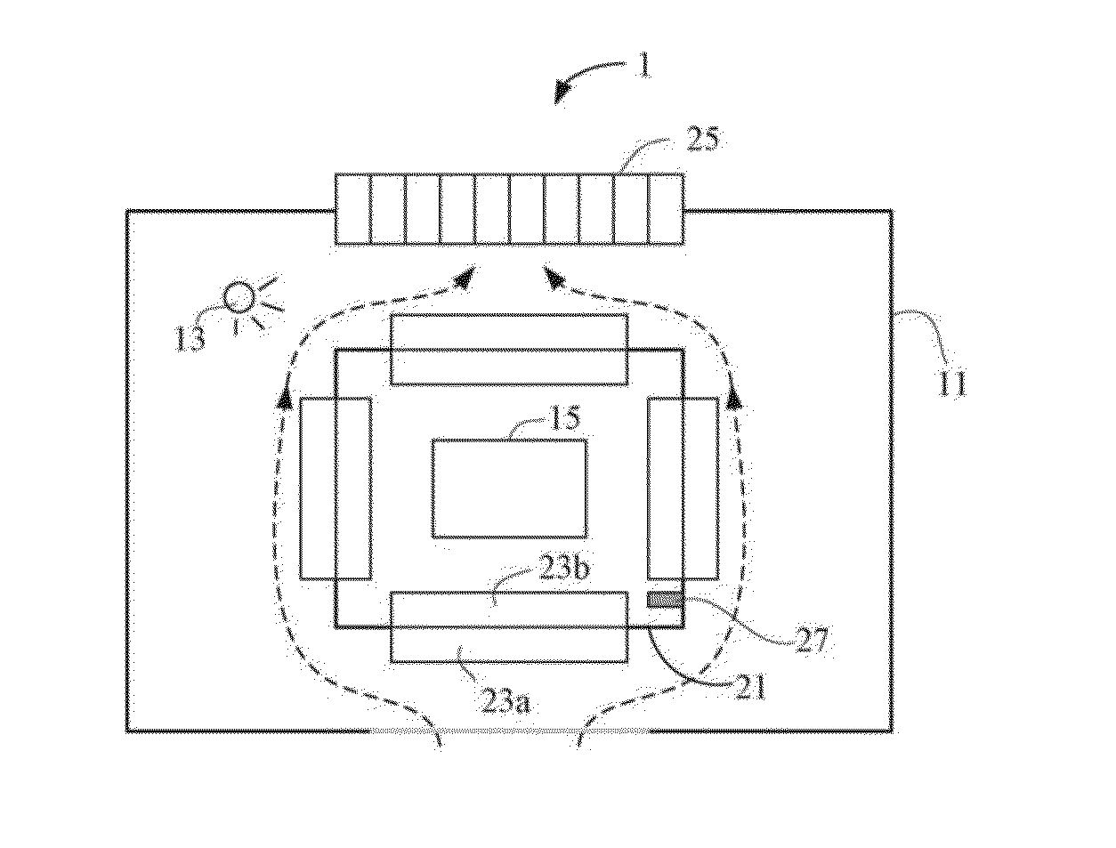
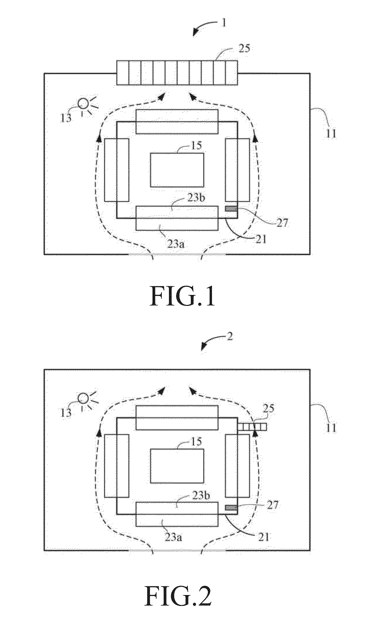
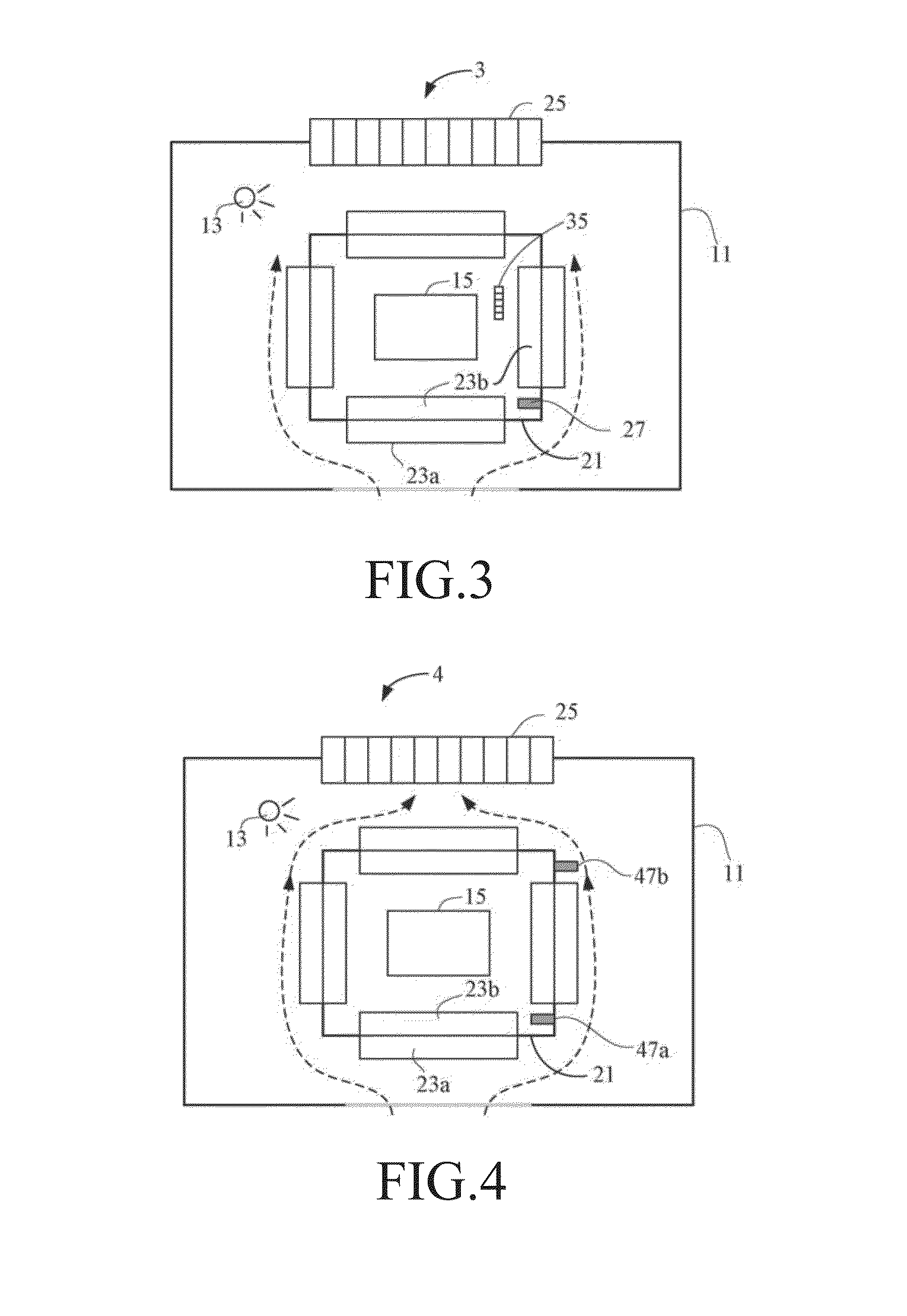
[0024]The present invention provides a heat dissipation assembly and a projection apparatus with the same. In the following descriptions, the present invention will be explained with reference to the embodiments thereof. However, it should be appreciated that the following descriptions of these embodiments are only intended to illustrate but not to limit the present invention. Meanwhile, in the following embodiments and the attached drawings, elements unrelated to the present invention are omitted from depiction; and dimensional relationships among individual elements in the attached drawings are illustrated only for ease of understanding, but not to limit the actual scale.

[0025]The first embodiment of the present invention is a projection apparatus 1, a schematic view of which is shown in FIG. 1. The projection apparatus 1 comprises a housing 11, a light source 13, an optical element set 15 and a heat dissipation assembly. The housing 11 is adapted to receive and protect components...


PUM


Abstract

A heat dissipation assembly for a projection apparatus is provided. The projection apparatus includes a light source, optical elements and a heat dissipation assembly. The heat dissipation assembly includes a case, a heat dissipation element, a fan and a temperature controlling unit. The optical elements transmit a light beam generated by the light source, and thereby generate heat. The heat dissipation assembly is adapted for heat dissipation correspondingly. In the heat dissipation assembly, the case protects the optical elements from being polluted by the dust during heat dissipation. The temperature controlling unit senses the surrounding temperature to control the fan for cooling the heat dissipation element, and the durability of the optical elements are thereby enhanced.

Description

CROSS-REFERENCES TO RELATED APPLICATIONS[0001]The present application is a continuation-in-part application of U.S. patent application Ser. No. 13 / 313,212, filed on Dec. 7, 2011, the entire contents of which are incorporated herein by reference and priority to which is hereby claimed. Application Ser. No. 13 / 313,212 claims priority under 35 U.S.C. §119 to Taiwanese Application No. 100101370, filed on Jan. 14, 2011, the disclosures of which are also incorporated by reference herein in their entirety and priority to which is also claimed hereby.BACKGROUND OF THE INVENTION[0002]1. Field of the Invention[0003]The present invention relates to a heat dissipation assembly, and in particular, to a heat dissipation assembly for use in a projection apparatus.[0004]2. Descriptions of the Related Art[0005]Because consumers have gravitated towards projection apparatuses with higher definition and more vivid colors, projection apparatuses have had to be designed to keep competitive in the market....

Claims


Application Information

Patent Timeline
Patent Type & Authority Applications(United States)
IPC IPC(8): G03B21/16G02B26/00G02B27/00G03B21/20
CPCG03B21/16G02B27/0006G02B26/008G03B21/2093H04N9/3144G03B21/20
Inventor LIN, CHIA-JUICHANG, HSIU-MINGHSU, MAO-SHAN
Owner DELTA ELECTRONICS INC
Why Eureka
Try Eureka