Light-emitting apparatus and a related projection system

Active Publication Date: 2016-01-28
APPOTRONICS CORP LTD
View PDF5 Cites 35 Cited by
  • Summary
  • Abstract
  • Description
  • Claims
  • Application Information

AI Technical Summary

Benefits of technology

[0032]Because the supplemental light beam emitted by the supplemental laser source has a relatively small cross-section, the first region of the light guiding device, which has a relatively small size, can direct the supplemental light to the wavelength conversion device; while the excitation light beam generated by the excitation light source, the converted light beam emitted by the wavelength conversion device, and at least a part of the supplemental light scattering reflected by the wavelength conversion layer have relatively lar

Problems solved by technology

However, currently used yellow phosphor material is usually a YAG (yttrium aluminum garnet) phosphor; in the yellow light generated by YAG phosphor under excitation, the component in the red wavelength range is relatively weak, so that when such light is used in projection and display applications, the red light generated by light division or the white light g

Method used


Image

  • Light-emitting apparatus and a related projection system
  • Light-emitting apparatus and a related projection system
  • Light-emitting apparatus and a related projection system

Examples


Example

First Embodiment

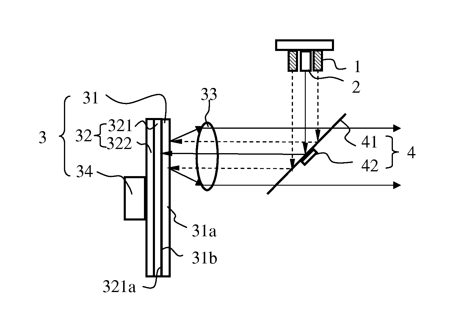
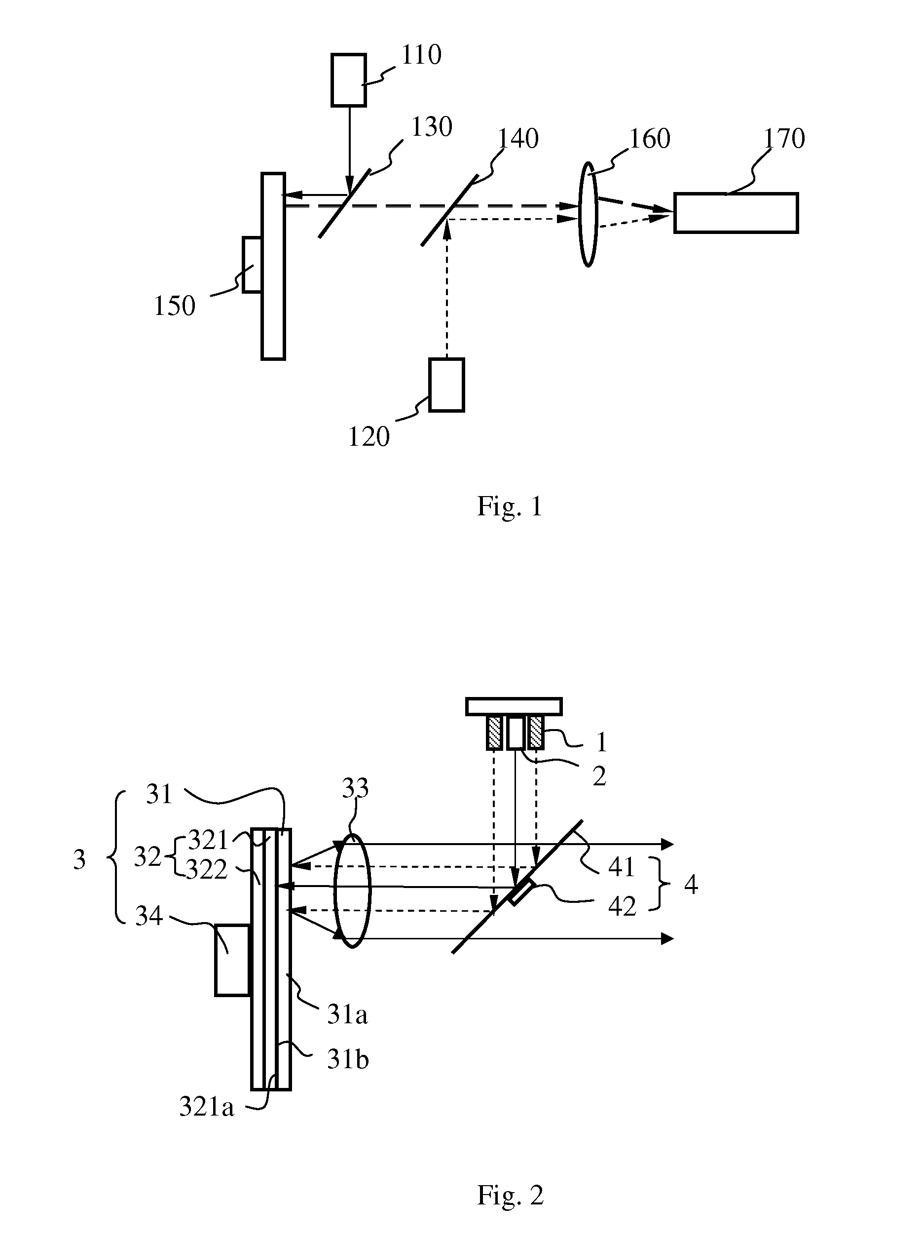
[0040]Refer to FIG. 2, which illustrates the structure of a light emitting device according to an embodiment of the present invention.

[0041]The light emitting device includes an excitation light source 1, a first supplemental laser source 2, wavelength conversion device 3 and light guiding device 4.

[0042]The excitation light source 1 generates an excitation light. The first supplemental laser source 2 generates a first light. To provide a high brightness light emitting device, the excitation light source 1 uses an array of a relatively large number of light emitting elements. Because the required amount of first light, which acts as a supplemental light to improve the color of the output light, is relatively small, the number of laser diodes in the first supplemental laser source 2 is far fewer that the number of light emitting elements in the light emitting element array of the excitation light source 1. In this embodiment, the excitation light source 1 is a blue la...

Example

Second Embodiment

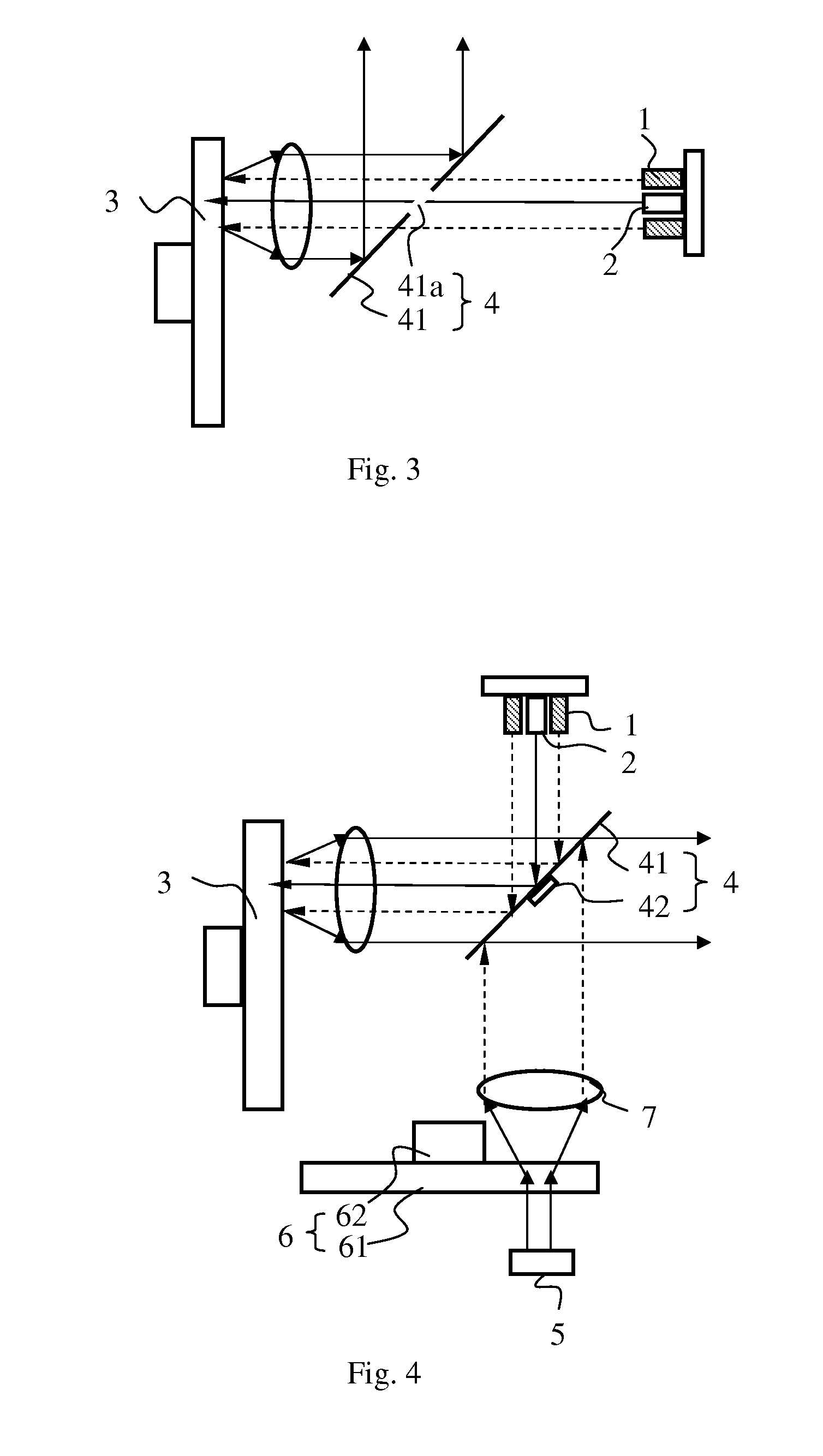
[0065]Refer to FIG. 4, which illustrates the structure of a light emitting device according to another embodiment of the present invention. The light emitting device includes an excitation light source 1, a first supplemental laser source 2, a wavelength conversion device 3 and a light guiding device 4.

[0066]Differences between this embodiment and the embodiment of FIG. 2 include:

[0067]The light emitting device further includes a second supplemental laser source 5 and a scattering device 6. The scattering device 6 includes a scattering layer 61 for scattering the second light generated by the second supplemental laser source 5. The first filter plate 41 of the light guiding device 4 additionally reflects the second light. The scattered second light is incident on the first filter plate 41 of the light guiding device 4 on a side facing away from the converted light, and is reflected into the second optical path; it is combined with the converted light and the first l...


PUM


Abstract

A light-emitting apparatus and a related projection system. The light-emitting apparatus comprises an excitation light source generating an excitation light and a first supplemental laser source generating a first light; a wavelength conversion apparatus comprising a first wavelength conversion layer for absorbing the excitation light to generate a converted light without absorbing the first light; the wavelength conversion layer receiving at one side thereof the excitation light and the first light and emits at same side at least a portion of the first light; a light guide apparatus comprising a smaller first area and a larger second area, the first light and the excitation light respectively entering the first and second areas via a first optical path, and being respectively guided by the first and second areas to the wavelength conversion apparatus; the second area also guiding the converted light and the reflected first light to a second optical path.

Description

BACKGROUND OF THE INVENTION[0001]1. Field of the Invention[0002]This invention relates to illumination and projection technologies, and in particular, it relates to a light emitting device and related projection system.[0003]2. Description of Related Art[0004]Using a blue light to excite a yellow phosphor material to generate a yellow light, and then dividing the yellow light into a green light and a red light, or combining the yellow light with the blue light to generate a white light, are commonly used techniques for light sources in current projection and display fields. However, currently used yellow phosphor material is usually a YAG (yttrium aluminum garnet) phosphor; in the yellow light generated by YAG phosphor under excitation, the component in the red wavelength range is relatively weak, so that when such light is used in projection and display applications, the red light generated by light division or the white light generated by light combination are not completely satis...

Claims


Application Information

Patent Timeline
IPC IPC(8): G03B21/20F21V7/22F21V9/16F21V13/08
CPCG03B21/2066F21V9/16G03B21/204F21V7/22F21V13/08F21V13/14F21V9/30G02B5/285G02B26/008G02B27/0905G02B27/1006H01S5/0071H01S5/4087H04N9/3158H04N9/3161H04N9/3164H01S5/0087
Inventor HU, FEI
Owner APPOTRONICS CORP LTD
Why Eureka
Try Eureka