Restoration filter generation device and method, image processing device and method, imaging device, and non-transitory computer-readable medium

Active Publication Date: 2016-01-28
FUJIFILM CORP
View PDF2 Cites 3 Cited by
  • Summary
  • Abstract
  • Description
  • Claims
  • Application Information

AI Technical Summary

Benefits of technology

The present invention provides a device and method for generating a restoration filter that can prevent overcorrection of the MTF value of image data for each color when performing the restoration process on the luminance system image data. The restoration filter is designed to suppress the MTF value of the image data for each color to 1.0 or less at least in the region of the particular spatial frequency or less. This prevents overcorrection of the MTF value of the image for each color and ensures that an excessive emphasis of the MTF value does not occur for any color. The device includes an amplification factor acquisition device that acquires the amplification factor of the MTF value for each spatial frequency with respect to image data for each color, and the restoration filter is generated based on the frequency characteristics of the amplification factors. The invention also provides an image processing device and method, an imaging device, and a computer-readable medium for generating the restoration filter.

Problems solved by technology

However, the image processing device in PTL 1 performs the point-image restoration process only on the luminance system image, and therefore, there is a fear that an overcorrection occurs for a particular wavelength (color).

Method used


Image

  • Restoration filter generation device and method, image processing device and method, imaging device, and non-transitory computer-readable medium
  • Restoration filter generation device and method, image processing device and method, imaging device, and non-transitory computer-readable medium
  • Restoration filter generation device and method, image processing device and method, imaging device, and non-transitory computer-readable medium

Examples


first embodiment

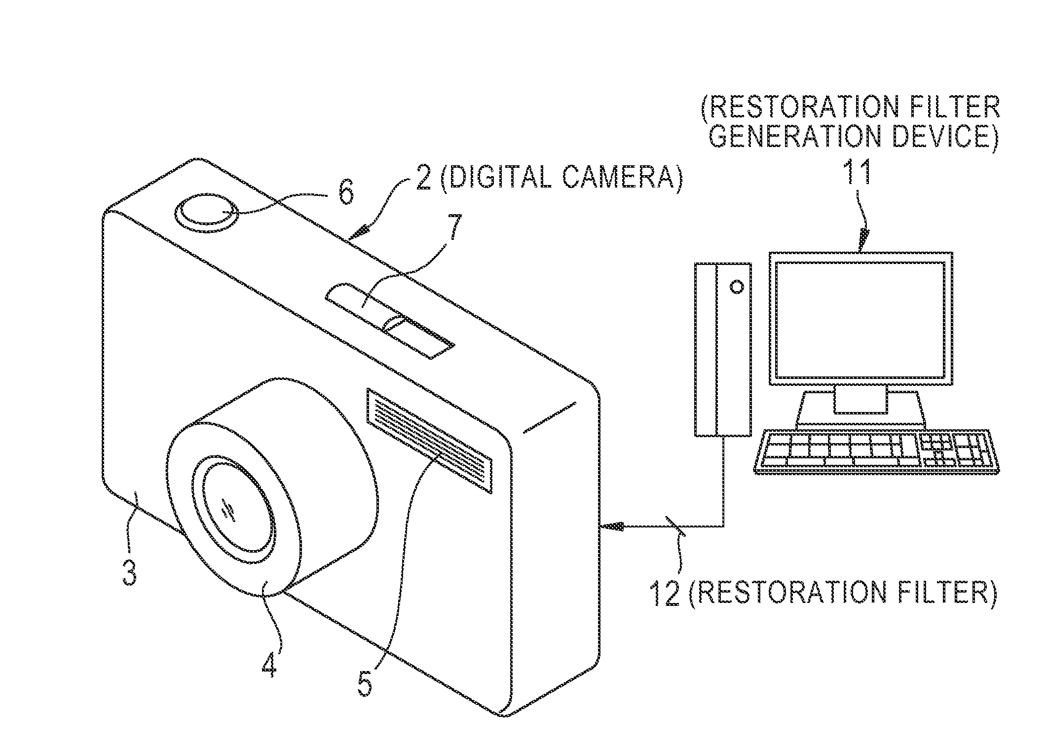
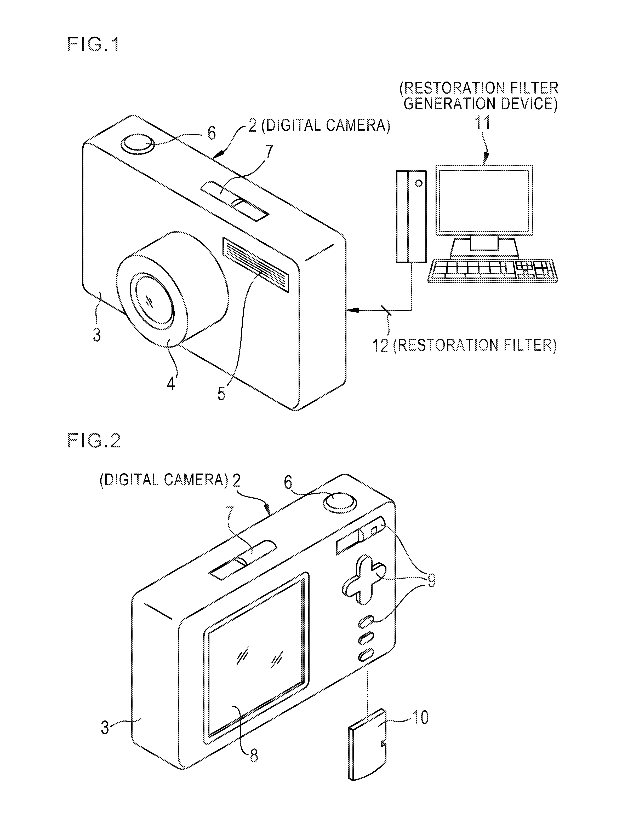
[0052]In FIG. 1 and FIG. 2, a digital camera 2 corresponds to an imaging device according to the present invention. On the front surface of a camera body 3 of the digital camera 2, a lens barrel 4 including an optical system and the like, a strobe light emission unit 5 and the like are provided. On the top surface of the camera body 3, a shutter button 6, a power switch 7 and the like are provided.

[0053]On the back surface of the camera body 3, a display unit 8, an operation unit 9 and the like are provided. In an image-taking standby state, the display unit 8 functions as an electronic viewfinder, and displays a live view image (also referred to as a through image). Further, during image review, an image is reproduced and displayed on the display unit 8, based on the image data recorded in a memory card 10.

[0054]The operation unit 9 is composed of a mode switch, a cross key, an execution key and the like. The mode switch is operated for changing the operation mode of the digital ca...

second embodiment

[0105]Next, a restoration filter generation device according to a second embodiment of the present invention is explained. The above restoration filter 12 according to the first embodiment shown in the (B) portion of FIG. 9 is designed to correspond to the lens MTFs 47R, 47G also, which are higher in the MTF value than the lens MTF 47B in a high frequency region. Therefore, since the restoration filter 12 is designed such that the amplification factor in a high frequency region (a low SN ratio region in FIG. 15) is high, there is a fear that an excessive frequency emphasis is applied in a region where the SN ratio of the B signal is low (hereinafter, referred to as a low SN ratio region, see FIG. 15) and thereby the noise of the B signal is amplified.

[0106]Hence, the restoration filter generation device according to the second embodiment generates a restoration filter that can prevent the side effect that the frequency characteristic of a restoration filter designed on the basis of ...

third embodiment

[0129]Next, a restoration filter generation device according to a third embodiment of the present invention is explained. As shown in FIG. 16, when the point-image restoration process is performed using the above restoration filter 62 according to the second embodiment, the application of an excessive frequency emphasis in the low SN ratio region for the B signal is prevented, but on the contrary, frequency emphasis is not applied in the frequency region for the R and G signals that corresponds to the low SN ratio region. Therefore, there is a fear that the R and G signals attenuate. Further, as described above, when the point-image restoration process is performed using the above restoration filter 12 according to the first embodiment, there is a fear that an excessive frequency emphasis is applied in the low SN ratio region for the B signal and the noise for the B signal is amplified.

[0130]Hence, the restoration filter generation device according to the third embodiment generates ...


PUM


Abstract

A restoration filter generation device which generates a restoration filter for performing a restoration process on luminance system image data, the restoration process being based on a point-image distribution in an optical system, the luminance system image data being image data relevant to luminance and being generated based on image data for each color of multiple colors, the restoration filter generation device including an MTF acquisition device which acquires a modulation transfer function MTF for the optical system; and a restoration filter generation device which generates the restoration filter based on the modulation transfer function MTF, the restoration filter suppressing an MTF value of image data for each color of the multiple colors to 1.0 or less at least in a region of a particular spatial frequency or less, the image data for each color of the multiple colors corresponding to the luminance system image data after the restoration process.

Description

CROSS-REFERENCE TO RELATED APPLICATIONS[0001]This application is a Continuation of PCT International Application No. PCT / JP2013 / 080647 filed on Nov. 13, 2013, which claims priority under 35 U.S.C §119(a) to Japanese Patent Application No. 2013-042185 filed on Mar. 4, 2013. Each of the above application(s) is hereby expressly incorporated by reference, in its entirety, into the present application.BACKGROUND OF THE INVENTION [0002]1. Field of the Invention[0003]The present invention relates to a restoration filter generation device and method for generating a restoration filter to be used in a restoration process, an image processing device and method for performing the restoration process using the restoration filter, an imaging device including the image processing device, and a non-transitory computer-readable medium for generating the restoration filter.[0004]1. Description of the Related Art[0005]In an image obtained by the imaging of a subject with an imaging device such as a d...

Claims


Application Information

Patent Timeline
IPC IPC(8): G06T5/00G06T5/20H04N1/58H04N9/04
CPCG06T5/003H04N9/045G06T2207/10024G06T5/20G06T2207/20024H04N1/58H04N23/81H04N23/632H04N25/615H04N25/6153H04N23/843G06T5/73H04N25/60H04N9/646
Inventor NARUSE, YOUSUKEHAYASHI, KENKICHISUGIMOTO, MASAHIKO
Owner FUJIFILM CORP
Why Eureka
Try Eureka