Method of manufacturing multilayer board, multilayer board, and electromagnet

Active Publication Date: 2016-01-28
MURATA MFG CO LTD
View PDF9 Cites 5 Cited by
  • Summary
  • Abstract
  • Description
  • Claims
  • Application Information

AI Technical Summary

Benefits of technology

[0007]Accordingly, preferred embodiments of the present invention provide a method of manufacturing a multilayer board which significantly reduces or prevents tilting of linear conductors in a stacking direction during thermocompr

Problems solved by technology

If the linear conductors tilt as described above, there is a possibility that the linear conductors adja

Method used


Image

  • Method of manufacturing multilayer board, multilayer board, and electromagnet
  • Method of manufacturing multilayer board, multilayer board, and electromagnet
  • Method of manufacturing multilayer board, multilayer board, and electromagnet

Examples


Embodiment Construction

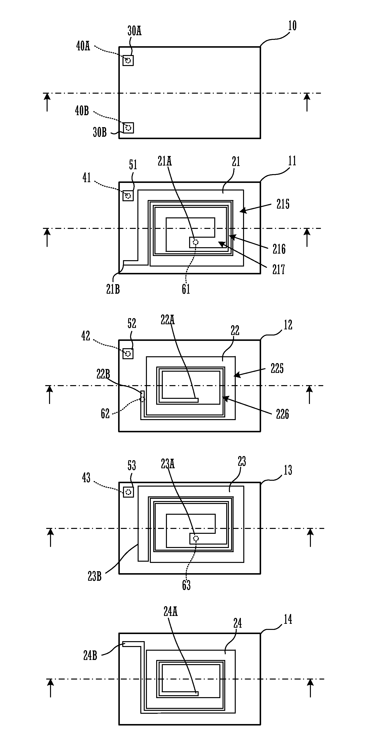
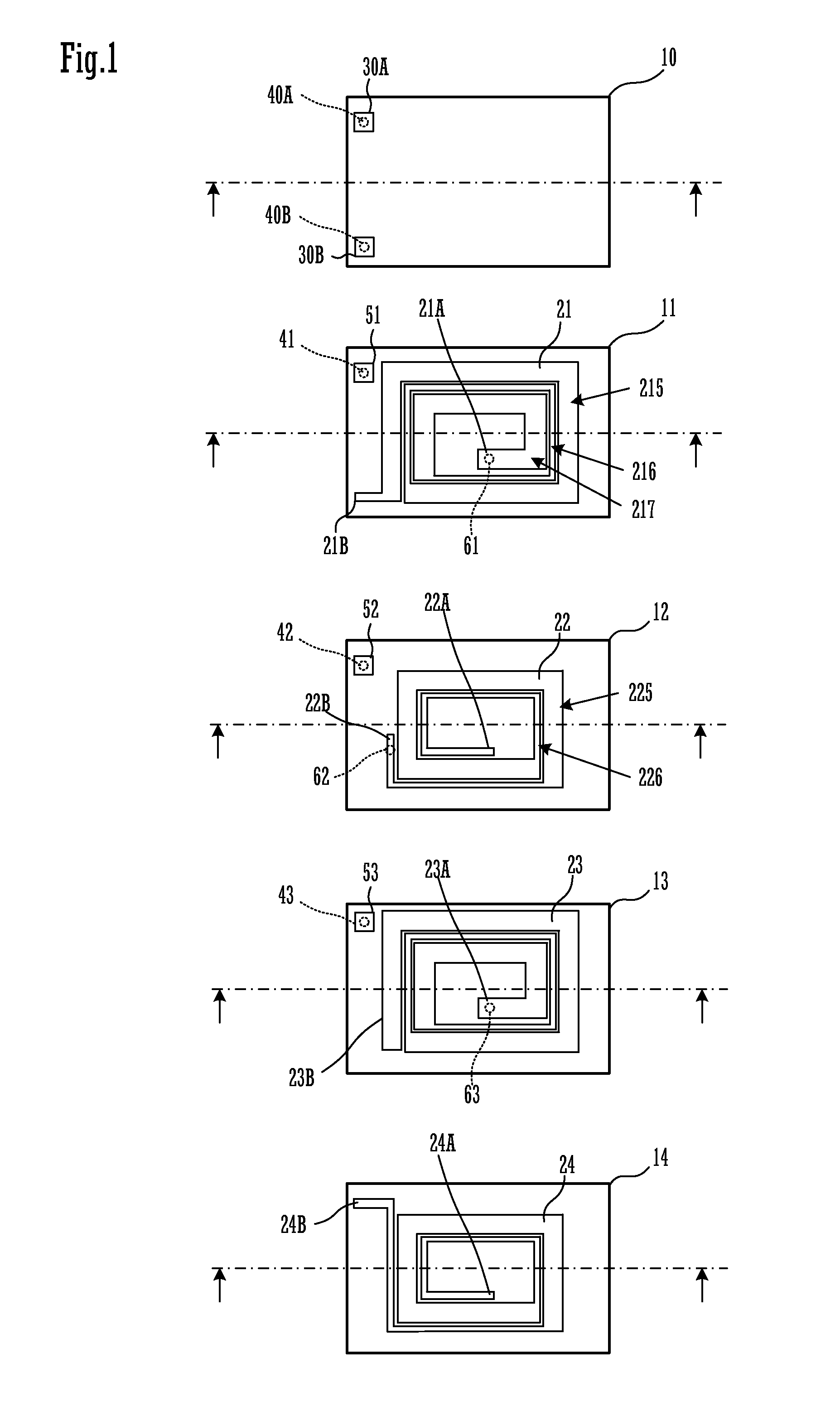
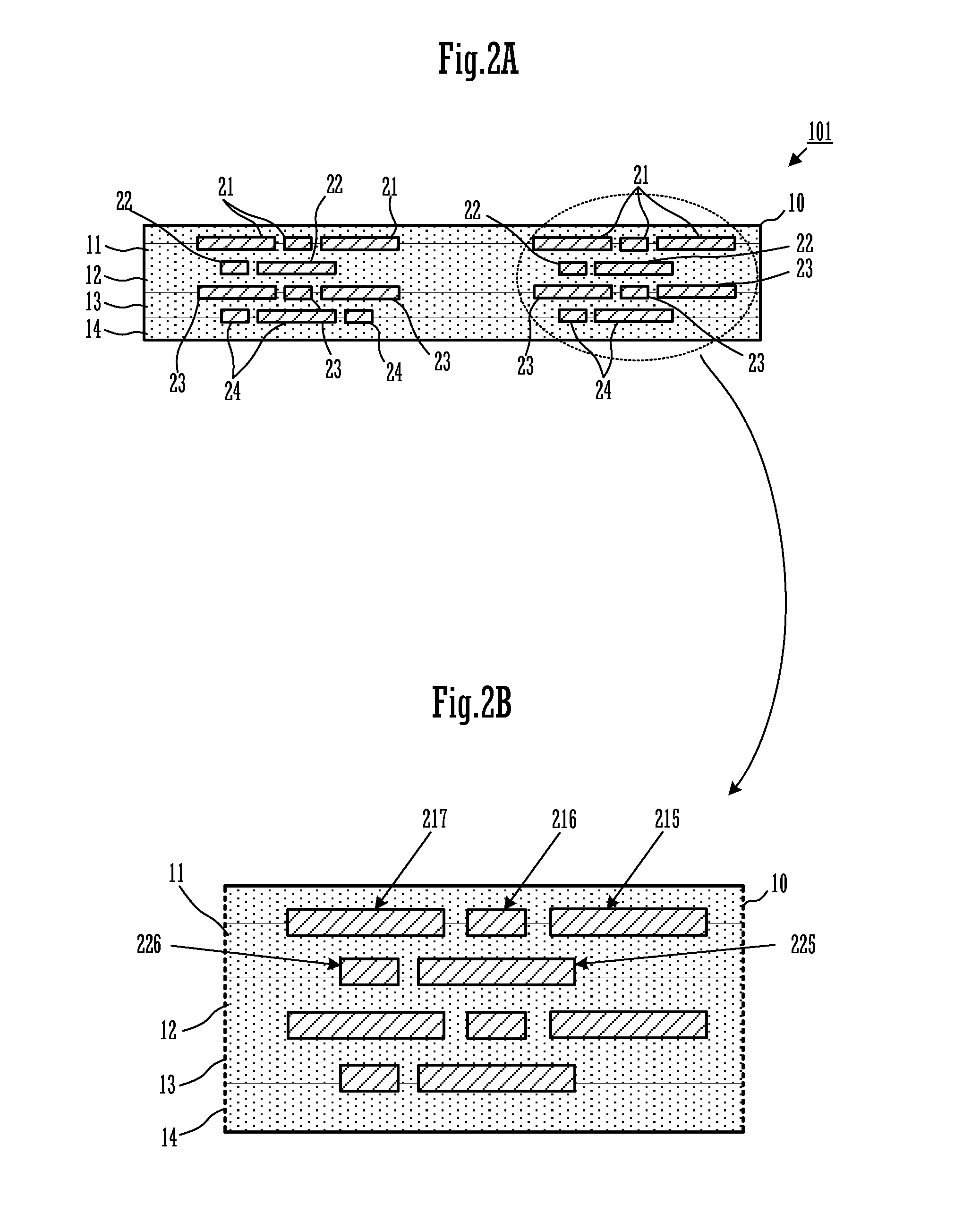
[0025]Hereinafter, multilayer boards according to preferred embodiments of the present invention will be described. FIG. 1 is exploded planar views of respective base material layers of a multilayer board 101, and FIG. 2A is a cross-sectional view of the multilayer board 101 at positions shown by alternate long and short dash lines in FIG. 1. FIG. 2B is an enlarged view of a portion of a region 100 shown by a dashed line in FIG. 2A.

[0026]The multilayer board 101 includes a base material layer 10, a base material layer 11, a base material layer 12, a base material layer 13, and a base material layer 14 which are stacked in this order from the upper surface side. The base material layer 10, the base material layer 11, the base material layer 12, the base material layer 13, and the base material layer 14 are preferably made of the same type of a thermoplastic resin, for example. The thermoplastic resin is, for example, a liquid crystal polymer resin. Examples of types of thermoplastic ...


PUM

PropertyMeasurementUnit
Widthaaaaaaaaaa
Widthaaaaaaaaaa
Thicknessaaaaaaaaaa

Abstract

In a linear conductor forming step, a wide portion having a relatively large line width and a narrow portion having a relatively small line width are formed in each of a plurality of linear conductors. In addition, in a multilayer board, in base material layers adjacent to each other in a stacking direction, the wide portion overlaps the narrow portion on the adjacent base material layer, and end portions of the wide portions at both sides of the narrow portion in a line width direction, in a planar view. The wide portions are disposed such that the end portions thereof overlap each other in the stacking direction and resistance of a fluid thermoplastic resin increases. The narrow portion is located between the wide portions in the stacking direction.

Description

BACKGROUND OF THE INVENTION[0001]1. Field of the Invention[0002]The present invention relates to a method of manufacturing a multilayer board including a plurality of stacked base material layers made of a thermoplastic resin, a multilayer board, and an electromagnet.[0003]2. Description of the Related Art[0004]A coil which is provided by patterning a conductor on an insulator is known. For example, Japanese Unexamined Patent Application Publication No. 4-368105 describes a spiral coil which is provided by patterning a linear conductor in a spiral manner on both surfaces of a polyimide film and performing interlayer connection therebetween.[0005]However, when a plurality of base material layers made of a thermoplastic resin are stacked and thermocompression bonding is performed, the thermoplastic resin flows during the thermocompression bonding, and thus linear conductors may be tilted in a stacking direction. If the linear conductors tilt as described above, there is a possibility ...

Claims


Application Information

Patent Timeline
IPC IPC(8): H01F41/04H01F7/06H01F41/02
CPCH01F41/041H01F2007/068H01F41/0233H01F7/06H05K1/165H05K3/4617H05K3/4632H05K2201/0129H01F17/0013H01F41/042H01F2017/0073
Inventor NISHINO, KOSUKEYOSUI, KUNIAKI
Owner MURATA MFG CO LTD
Why Eureka
Try Eureka