Switching power supply device

a power supply device and power supply technology, applied in the direction of electric variable regulation, process and machine control, instruments, etc., can solve the problems of low switching frequency, noise audible to the human ear, and takes time, so as to prevent erroneous operation

Inactive Publication Date: 2016-01-28
ROHM CO LTD
View PDF15 Cites 32 Cited by
  • Summary
  • Abstract
  • Description
  • Claims
  • Application Information

AI Technical Summary

Benefits of technology

[0032]In view of the above-mentioned problems encountered by the inventors of the present invention, a further object of the present invention disclosed herein is to provide a power control IC that can prevent erroneous operation during switching of operation modes, and to provide a switching power supply device and an electronic appliance employing such a power control IC.

Problems solved by technology

Inconveniently, however, once this power-saving function is activated, it takes time for the feedback voltage FB to fall below the reference voltage REF.
This results in a low switching frequency under a light load, possibly causing noise audible to the human ear.
This results in diminished efficiency.
Thus, turning the output transistor N1 only once does not allow sufficient energy to be stored in the coil L1, and consequently the feedback voltage FB may not rise above the reference voltage REF.
This causes diminished efficiency.
Inconveniently, however, with the first conventional method, the overshoot suppression function is not activated before an overshoot is actually detected.
This results in a delay in the overshoot suppression action, diminishing its effect.
This invites increased cost and increased current consumption.
However, in the switching power supply device 100 of a non-linear control type, the switching frequency tends to vary according to operation status, and thus, with the second conventional method, an overshoot suppression function may be activated erroneously.
This cannot be coped with by the second conventional method.
However, in the conventional switching power supply device, the highest priority is given to securing safety against, for example, a short circuit between output and ground: an overcurrent protection circuit is kept on all the time even under a light load, and a certain amount of driving current is consumed constantly.
Thus, with the conventional switching power supply device, the variation in current may cause unintended switching operation, possibly leading to increased output ripples.

Method used


Image

  • Switching power supply device
  • Switching power supply device
  • Switching power supply device

Examples


modified examples

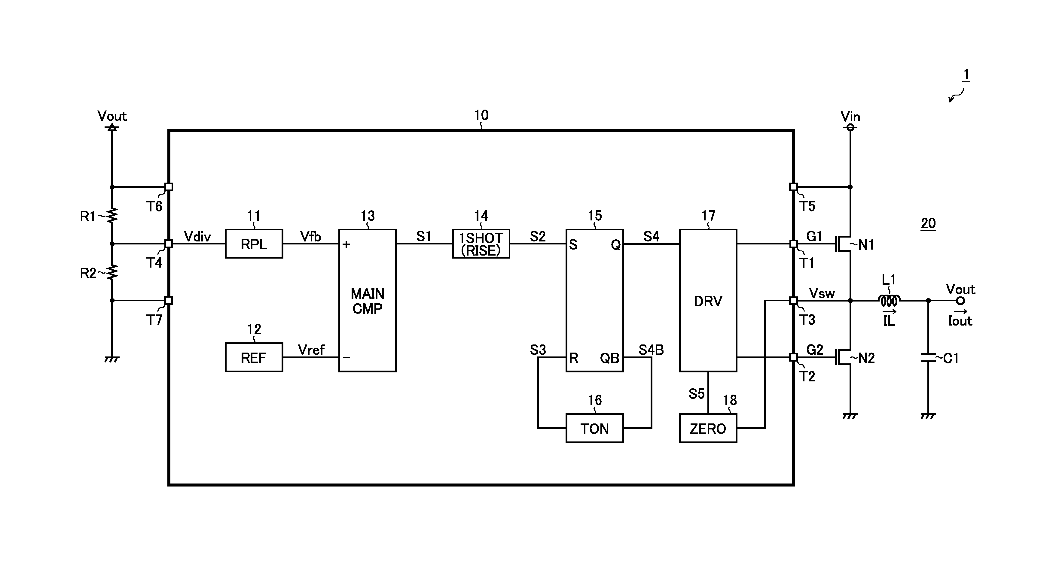
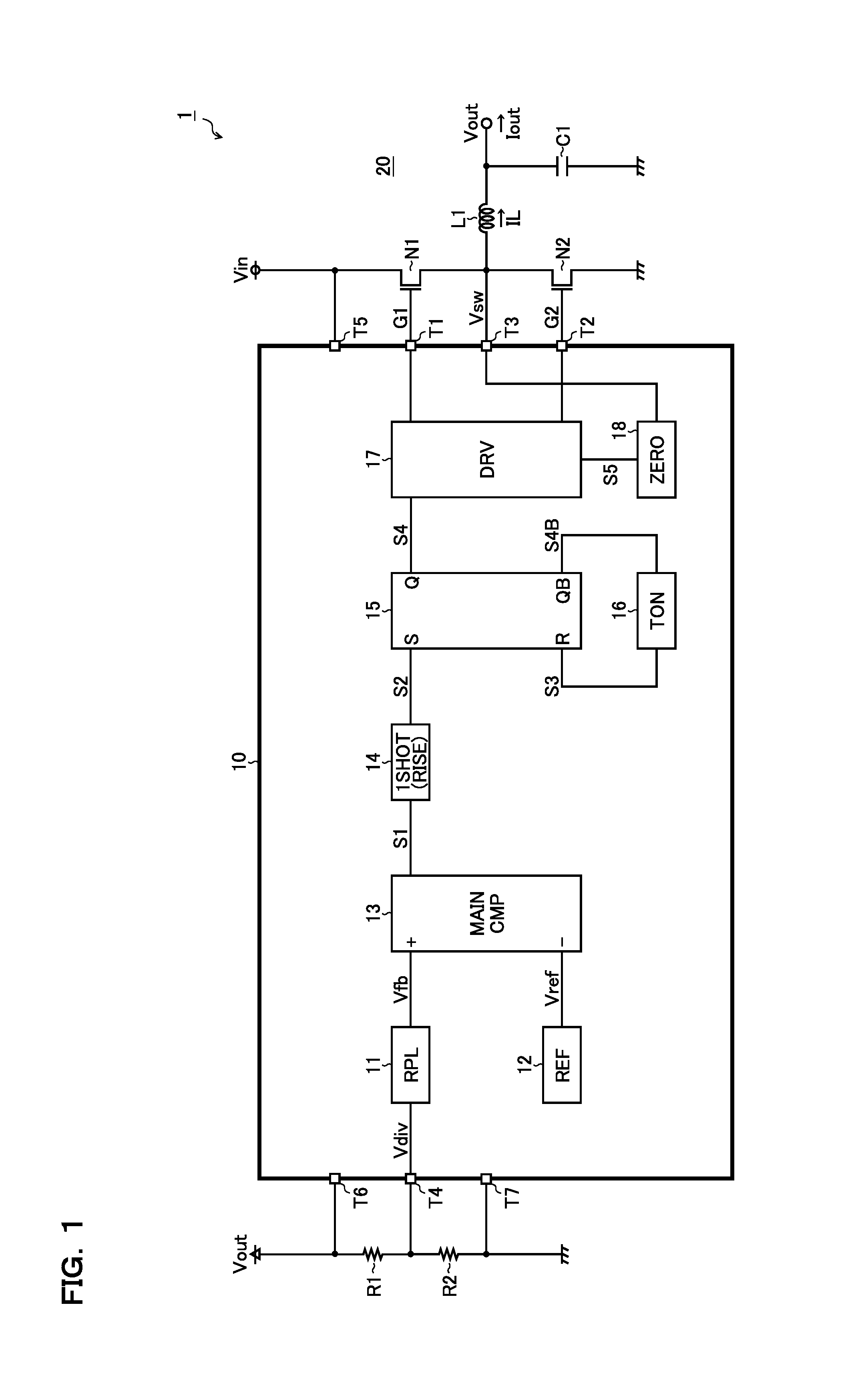
[0341]Although the embodiments described above deal with examples where the present invention is applied to a step-down switching power supply device adopting synchronous rectification, this is not meant to limit the application of the present invention; asynchronous rectification may instead be adopted as a switching driving method, or the output stage of the switching power supply device may be configured to be of a step-up type or a step-up / step-down type.

[0342]The present invention can be implemented in any other manners than specifically described above by way of embodiments, and allows for many modifications within the spirit of the invention. That is, the embodiments described above should be considered to be in every aspect simply illustrative and not restrictive, and it should be understood that the technical scope of the present invention is defined not by the description of embodiments given above but by the appended claims and encompasses any modifications in the sense a...


PUM


Abstract

A power control IC has a switching control circuit of a fixed on-period type which generates an output voltage from an input voltage by driving a coil by turning on and off an output transistor according to a result of comparison between a feedback voltage and a reference voltage, and a quieting circuit which forcibly turns on the output transistor by ignoring the result of comparison when, after an on-timing of the output transistor, a predetermined threshold time elapses without the next on-timing coming.

Description

[0001]This application is based on the following Japanese patent applications, the contents of which are hereby incorporated by reference:[0002](1) Japanese Patent Application No. 2014-152703, filed on Jul. 28, 2014[0003](2) Japanese Patent Application No. 2014-152705, filed on Jul. 28, 2014[0004](3) Japanese Patent Application No. 2014-152708, filed on Jul. 28, 2014BACKGROUND OF THE INVENTION[0005]1. Field of the Invention[0006]The present invention relates to switching power supply devices (switched-mode power supply device) of a non-linear control type.[0007]2. Description of Related Art[0008]FIG. 41 is a circuit block diagram showing one conventional example of a switching power supply device. Compared with switching power supply devices of a linear control type (e.g., a voltage mode control type and a current mode control type), switching power supply devices of a non-linear control type (e.g., a fixed on-period type, a fixed off-period type, and a hysteresis-window type) have ...

Claims


Application Information

Patent Timeline
Patent Type & Authority Applications(United States)
IPC IPC(8): H02M3/158
CPCH02M3/158H02M1/32H02M3/156H02M1/0032H02M3/1566Y02B70/10H02M3/1588
Inventor MURAKAMI, KAZUHIRO
Owner ROHM CO LTD
Why Eureka
Try Eureka