Eye tracking calibration

a technology for eye tracking and calibration, applied in the field of eye tracking calibration, can solve the problems of further processing, and achieve the effect of reducing the need for further calibration for individual users and improving tracking accuracy

Inactive Publication Date: 2016-02-04
EYE TRACKING ANALYSTS
View PDF4 Cites 67 Cited by
  • Summary
  • Abstract
  • Description
  • Claims
  • Application Information

AI Technical Summary

Benefits of technology

[0018](e) repeating steps a) to d) for one or more further different visual targets. Therefore, the record or calibration store can be added to in order to improve tracking accuracy and reduce the need for further calibration for individual users. The visual target may be a visual calibration target, for example. In other words, the visual target may be an item (e.g. part or whole of an image) with a specific purpose to draw a subject's gaze (e.g. star, dot, cross, etc.) However, the visual target may instead be an item (e.g. part or whole of an image) that has another or primary use. For example, the visual target may be an icon, box, selectable button with a known location that may also draw the gaze of the subject. ‘Pupil Centre Corneal Reflection’ (PCCR) eye tracking is an example technique that requires calibration although there are others. The method may be repeated for one or more additional or new subjects. The physical arrangement in space may be obtained by directly or indirectly measuring the subject (measuring the physical arrangement in space) or by otherwise retrieving measurement data. This may be in real time or from a recording, for example.

Problems solved by technology

However, when there isn't a close match then the stored records may still be used but may require further processing.

Method used


Image

  • Eye tracking calibration
  • Eye tracking calibration
  • Eye tracking calibration

Examples


first embodiment

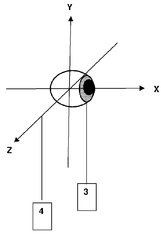
[0208]In the first embodiment, the method of estimation the physical arrangement in space of the subject is illustrated in FIG. 4. The positions of both the calibration subject's eyes 20 are measured with respect to an eye reference point 21 defined as the midpoint of the line joining the centre of the bounding rectangle 22 of each eye in the video image. The depth of the tracking subject's eyes is estimated by finding the Euclidean distance between the centre of a bounding rectangle 22 of each eye in the video image and dividing this length (measured in image-based pixel co-ordinates) by the Euclidean distance between the centre of the bounding rectangles of the tracking subject's eyes measured on the tracking subjects actual face (measured in the real-world co-ordinate system). The distance of the eye reference point from the camera z was then estimated using the perspective projection (Equation 1) below:

z=a+b*(Li / L)   (1)

[0209]where Li is the distance between the subject's eyes i...

second embodiment

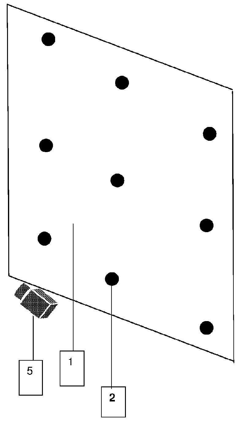
[0214]Another embodiment of the eye-tracking system uses a web-camera attached to a desktop computer or mobile device (e.g. Ea cellphone, smart phone or tablet computer). The camera captures a video of the user's face while they use a software application such as a web browser. The eye-tracking device detects the users' eyes in the video image and captures images of one or both eyes or makes eye-gaze measurement as the eyes look at one or more known calibration targets 2 (FIG. 1). A calibration target 2 (FIG. 1), could be a displayed token which the user looks at on the computer or mobile device display or the calibration target could be the co-ordinates of an on-screen selection using a touch screen or an input device such as a mouse or stylus. The eye tracker device may store eye-gaze measurements or images of the eye as it looks at known calibration targets 2 (FIG. 1) and store the corresponding physical arrangement in space of the subject, e.g. their position and / or orientation ...

third embodiment

[0216]Another embodiment may use a Template Matching algorithm where templates of the calibration subject's eye or eyes are captured as the calibration subject looks at one or more calibration targets 2 (FIG. 1) on a surface 1 (FIG. 1). When capturing the eye templates, the templates are stored together with the position and / or orientation and / or scale of the calibration subject's eye or eyes (or eye or eyes reference point) and co-ordinates of the calibration target 2 (FIG. 1) on the surface 1 (FIG. 1). This means that if the eye-tracker stores eye templates for one or more eye or eyes (or eye or eyes reference point) positions and / or orientations and / or scales then these templates can be stored and reused at a later time by any tracking subject who is positioned such that his / her eye or eyes (or eye or eyes reference point) are located at the same position, orientation and scale as one of the pre-calibrated positions, orientations and scales stored by the eye-tracking device durin...


PUM


Abstract

Method, system and apparatus for calibrating an eye tracker comprising presenting a subject with a visual target. Detemiining a physical arrangement in space of the subject. Obtaining an eye measurement of the subject. Storing a record of the subject's physical arrangement in space and data derived from the eye measurement of the subject, associated with the visual target presented to the subject. Repeating for one or more further different visual targets.

Description

FIELD OF THE INVENTION [0001]The present invention relates to a method and system for tracking the gaze or point of regard of a subject and in particular to the calibration of such eye-gaze or tracking systems.BACKGROUND OF THE INVENTION[0002]Eye-tracking is a topic of growing interest in the computer vision community. This is largely due to the wide range of potential applications. An eye-tracker device consists of sensors to make eye-gaze measurements and algorithmic techniques to map these eye-gaze measurements into real-world Cartesian space. Such eye-tracker devices can be used in a number of fields such as natural user interfaces for computerised systems, marketing research to assess customer engagement with visual marketing material, software usability studies, assessing product placement in supermarkets, attention monitoring in critical systems, attention monitoring within vehicles and in assistive and augmented communication devices for people with severe motor disabilities...

Claims


Application Information

Patent Timeline
Patent Type & Authority Applications(United States)
IPC IPC(8): A61B3/00A61B3/113G06F3/01G06K9/00
CPCA61B3/0025A61B3/113G06K9/00604G06K9/00617G06F3/013G06V40/19G06V40/197
Inventor COX, JOHN, STEPHEN
Owner EYE TRACKING ANALYSTS
Why Eureka
Try Eureka