Thermally-isolated anchoring systems with split tail veneer tie for cavity walls

a technology of split tail veneer and anchoring system, which is applied in the direction of building components, building reinforcements, construction, etc., can solve the problems of affecting the installation, affecting the integrity of the insulation system, and loosening of the stud, so as to prevent pin-point loading, prevent disengagement, and high tension and compression

Active Publication Date: 2016-02-04
HOHMANN & BARNARD INC
View PDF0 Cites 8 Cited by
  • Summary
  • Abstract
  • Description
  • Claims
  • Application Information

AI Technical Summary

Benefits of technology

[0033]It is the object of the present invention to provide a new and novel anchoring system assembly for a cavity wall structure, having an outer wythe of concrete masonry units, rubble stone or panels, that maintains structural integrity and provides high-strength connectivity and sealing.
[0035]It is a further object of the present invention to provide an anchoring system which is resistive to high levels of tension and compression, precludes pin-point loading, and, further, is detailed to prevent disengagement.
[0038]It is another feature of the present invention that the anchor assembly utilizes neoprene fittings and has only point contact with the metal studs thereby restricting thermal conductivity.

Problems solved by technology

However, under certain conditions, the system did not sufficiently maintain the integrity of the insulation.
In general, the pintle-receiving sheetmetal version of the Seismiclip interlock system served well, but in addition to the insulation integrity problem, installations were hampered by mortar buildup interfering with pintle leg insertion.
This resulted, upon experiencing lateral forces over time, in the loosening of the stud.
While the gapping was largely resolved by placing a self-sealing, dual-barrier polymeric membrane at the site of the legs and the mounting hardware, with increasing thickness in insulation, this patchwork became less desirable.
However, as there is no thermal break, a concomitant loss of the insulative integrity results.
The prior art does not provide the wall anchor assembly which is modifiable for use in varied cavity wall structures.
The prior art does not provide the present novel cavity wall construction system as described herein below.

Method used


Image

  • Thermally-isolated anchoring systems with split tail veneer tie for cavity walls
  • Thermally-isolated anchoring systems with split tail veneer tie for cavity walls
  • Thermally-isolated anchoring systems with split tail veneer tie for cavity walls

Examples


first embodiment

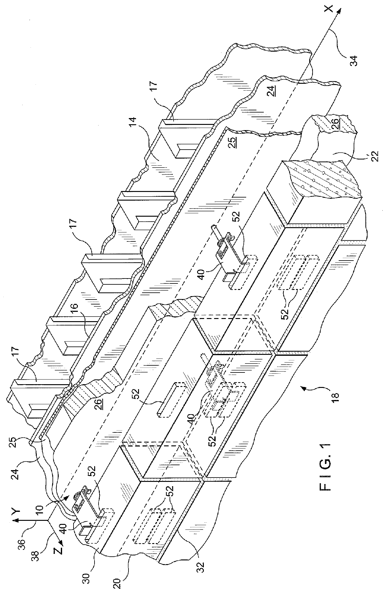
[0054]Referring now to FIGS. 1, 3, 4 and 5 illustrating the first embodiment and showing a surface-mounted, thermally-isolating anchor assembly for a cavity wall with a split veneer tie. This anchor is suitable for recently promulgated standards. The system, discussed in detail herein below, is a high-strength wall anchor for connection with an inter-engaging veneer tie. The wall anchor is either surface mounted onto an externally insulated dry wall inner wythe or installed onto an externally insulated masonry inner wythe (not shown).

[0055]As to the first embodiment, an exemplary cavity wall having an insulative layer of 3½ inches (approx.) and a total span of 6 inches (approx.) has been chosen for a discussion. This structure meets the R-factor requirements of the public sector building specification. On the other hand, use of the invention with other wall structures is contemplated. The anchoring system is referred to as high-span and generally identified by the numeral 10. For pu...

second embodiment

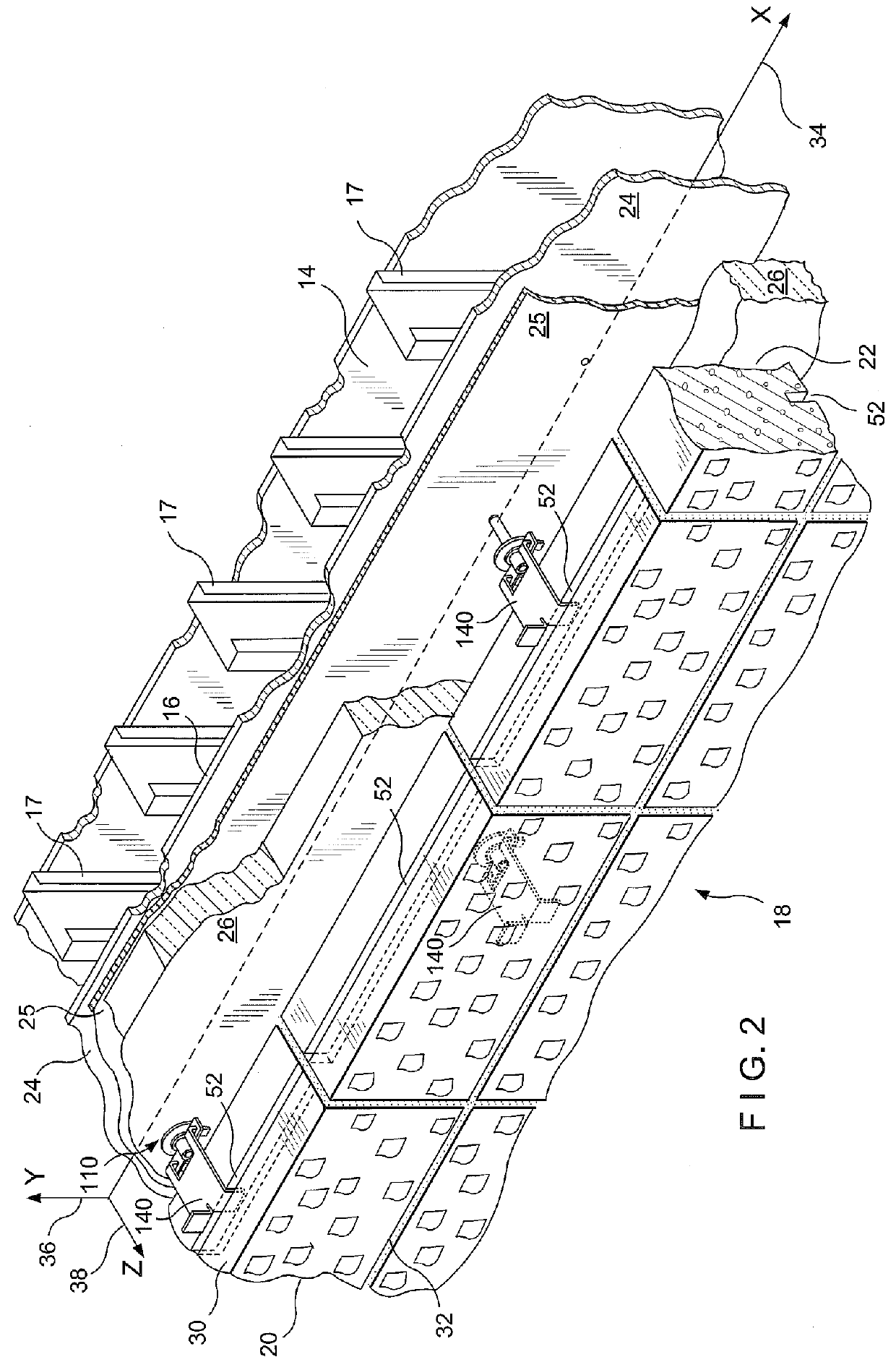
[0065]Illustrated in FIGS. 2, 6 and 7, the anchor is suitable for recently promulgated standards with more rigorous characteristics. The system of the second embodiment discussed in detail hereinbelow, is a high-strength wall anchor for connection with an interengaging veneer tie. The wall anchor is either surface mounted onto an externally insulated dry wall inner wythe (as shown in FIGS. 2 and 7) or installed onto an externally insulated masonry inner wythe.

[0066]Similar to the above-discussed first embodiment, FIG. 2 illustrates a cavity wall having a respective insulative layer with a respective total span. This structure meets the R-factor requirements of the public sector building specification. The anchoring system is referred to as high-span and generally referred to by the numeral 110. A cavity wall structure having an inner wythe or dry wall backup 14 with sheetrock or wallboard 16 and insulation 26 mounted on metal studs or columns 17 and an outer wythe of facing concrete...


PUM


Abstract

A high-strength thermally-isolating surface-mounted anchoring system for a cavity wall is disclosed. The thermally-isolated anchoring system is adaptable to various structures, including high-span applications, and for use with a split tail veneer tie. The anchoring system includes an anchor base and a stepped cylinder which sheaths the mounting hardware to limit insulation tearing and resultant loss of insulation integrity. The anchoring system is thermally-isolated through the use of multiple strategically placed compressible nonconductive seals or elements. Seals are also provided to preclude penetration of air, moisture, and water vapor into the wall structure.

Description

FIELD OF THE INVENTION[0001]The invention relates to anchoring systems used in a construction industry in general and specifically relates to the anchoring systems for insulated cavity walls.BACKGROUND OF THE INVENTION[0002]In the past, anchoring systems have taken a variety of configurations. Where the applications included masonry backup walls, wall anchors were commonly incorporated into ladder- or truss-type reinforcements and provided wire-to-wire connections with box-ties or pintle-receiving designs on the veneer side.[0003]In the late 1980's, surface-mounted wall anchors were developed by Hohmann & Barnard, Inc., now a MiTEK-Berkshire Hathaway Company, and patented under U.S. Pat. No. 4,598,518. The invention was commercialized under trademarks DW-10®, DW-10-X®, and DW-10-HS®. These widely accepted building specialty products were designed primarily for dry-wall construction, but were also used with masonry backup walls. For seismic applications, it was common practice to use...

Claims


Application Information

Patent Timeline
Patent Type & Authority Applications(United States)
IPC IPC(8): E04B1/41
CPCE04B1/4178E04B1/4157E04C5/01E04B1/4185E04B1/7612
Inventor HOHMANN, JR., RONALD, P.
Owner HOHMANN & BARNARD INC
Why Eureka
Try Eureka