Vacuum shaker systems

a vacuum shaker and shaker technology, applied in the direction of filtration separation, separation process, borehole/well accessories, etc., can solve the problems of not being able to achieve the effect of separation of solids and liquids, one type of machine will not be operative or effective in a different industry, and tend to ignore the quality of recovered fluids

Inactive Publication Date: 2016-02-04
FP MARANGONI INC
View PDF5 Cites 5 Cited by
  • Summary
  • Abstract
  • Description
  • Claims
  • Application Information

AI Technical Summary

Benefits of technology

[0030]In another embodiment, the system further includes a baffle operatively connected within the first and second vacuum hoses to prevent airflow / vacuum tugging between the first and second manifolds.
[0038]In yet another embodiment, the method includes the step of adjusting the frequency of opening and closing the pulse valve to control the time that drill cuttings are stalled on the shaker screen.

Problems solved by technology

The nuances of each general type of solid / liquid solution and each machine generally means that one type of machine will not be operative or effective within a different industry as, in many cases, unique problems exist in the handling of specific types of materials or solutions.
For example many screening machine designs have been designed to optimize recovery of the solid materials from within a slurry; however, this format tends to ignore the quality of the recovered fluid.
As such, it has generally not been considered how to effect separation of solids and liquids while maintaining or improving the quality of the fluid being recovered.
In the specific case of separating drilling fluid from drill cuttings, no commercially viable systems have been designed to provide effective pulsed vacuum assisted screening for the oil industry.
That is, while various screening machines used in different industries propose such certain features, a review of such machines reveals that if used with modern drilling fluids, that significant processing issues would result.
It has been determined that fines within recovered drilling fluid will generally negatively affect the quality of the drilling fluid that is recovered.
In addition, while it is desirable to minimize the formation of fines, a certain quantity of fines will always be present in the system which over time can cause significant problem to an operator.
However, with multiple shakers connected together and with varying lengths of vacuum hose that may be configured to the shakers, there remains a problem in preventing the plugging of vacuum lines over time as maintaining high velocity flow through each of the vacuum lines may be problematic particularly when multiple systems are configured together.
In addition, the nature of recovered drilling fluid may change dramatically as drilling advances through different formations.
As a result, and depending on the formation, the consistency and nature of the drilling fluid / drill cuttings may change over the course of a relatively short period of time.
For example, softer formations with a higher ROP may result in larger drilling cuttings whereas a harder formation with a lower ROP may result in smaller drill cuttings.
Thus, when conveying recovered fluids using a vacuum assisted shaker, it is a fact that vacuum recovery transport line sedimentation can be particularly difficult with the larger screen openings.
However, maintaining a high air velocity in the transport lines results in higher vacuum pressures at the manifold and tends to cause stalling of the drill cuttings on the shaker screens.
In pulsed screen systems that have been used previously, this problem is even more difficult as an operator is attempting to slow or temporarily stall the cuttings on the screen and then release them while at the same time maintain high air velocities in the slurry transport lines.
Further still, when finer screens are used (i.e. API 325 mesh), the surface tension between the fluid and the screen cannot be overcome readily by the acceleration, amplitude and mass combination of the shaker basket.
So while a coarser screen (i.e. API 100 mesh) allows more solids through and creates transport recovery line issues, finer screens (i.e. API 325 mesh) results in larger quantity of solids and increased fluid depth on the screen which complicates issues of screen plugging when a continuous vacuum is applied.
This patent also does not teach a means of controlling sedimentation in the vacuum lines.
This condition would result in line sedimentation and plugged off flow in the transport lines very quickly.
In addition, in this system, the vacuum system does not convey both air and liquid components through a common vacuum line.
Moreover, the patent does not describe sealing the sump to the atmosphere and thus, this system cannot effectively control the vacuum pressure within the sump as the pressure will neutralize with atmospheric pressure.
This patent also does not teach a means of controlling sedimentation in the vacuum lines.

Method used


Image

  • Vacuum shaker systems
  • Vacuum shaker systems
  • Vacuum shaker systems

Examples


Embodiment Construction

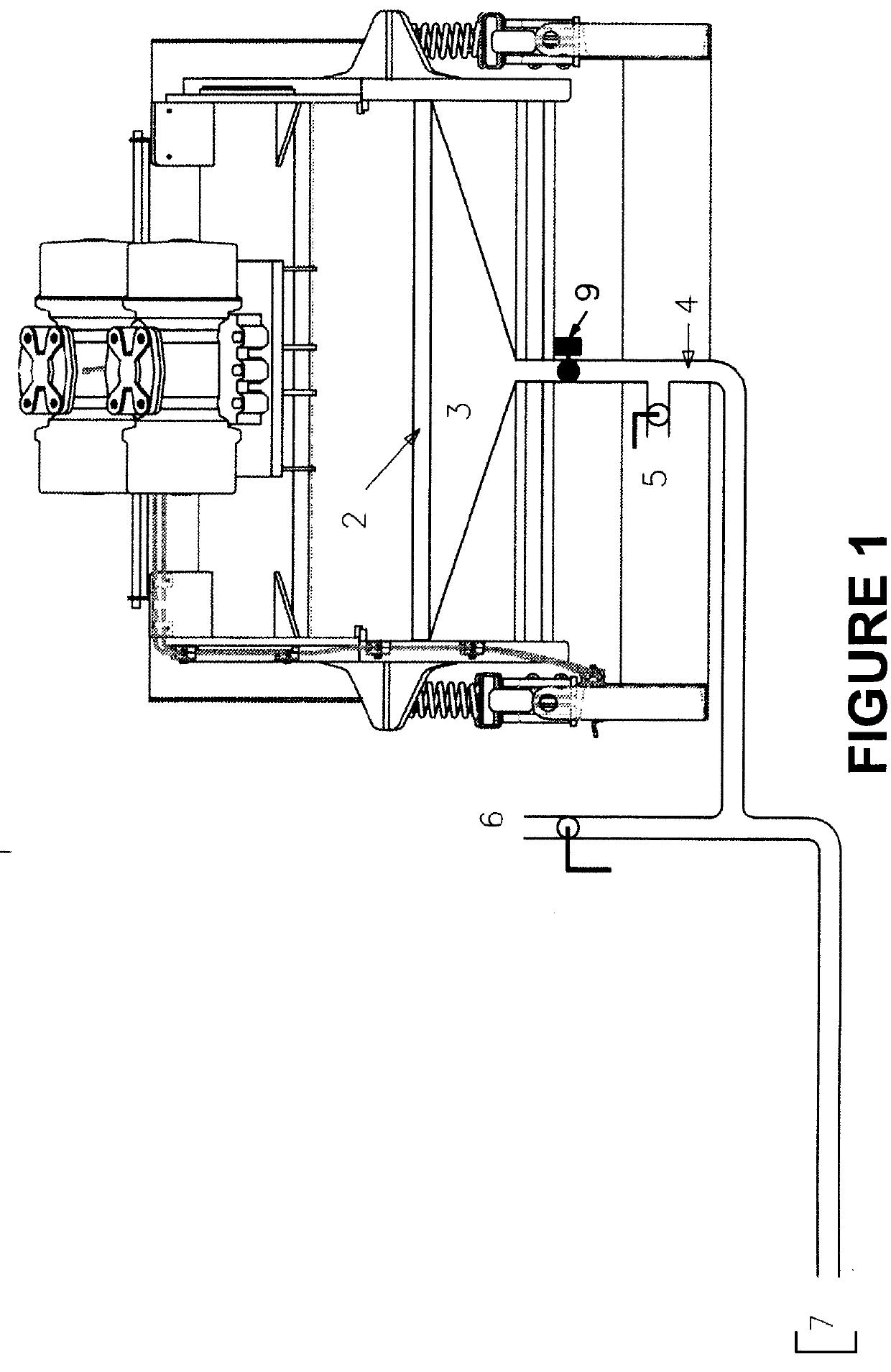
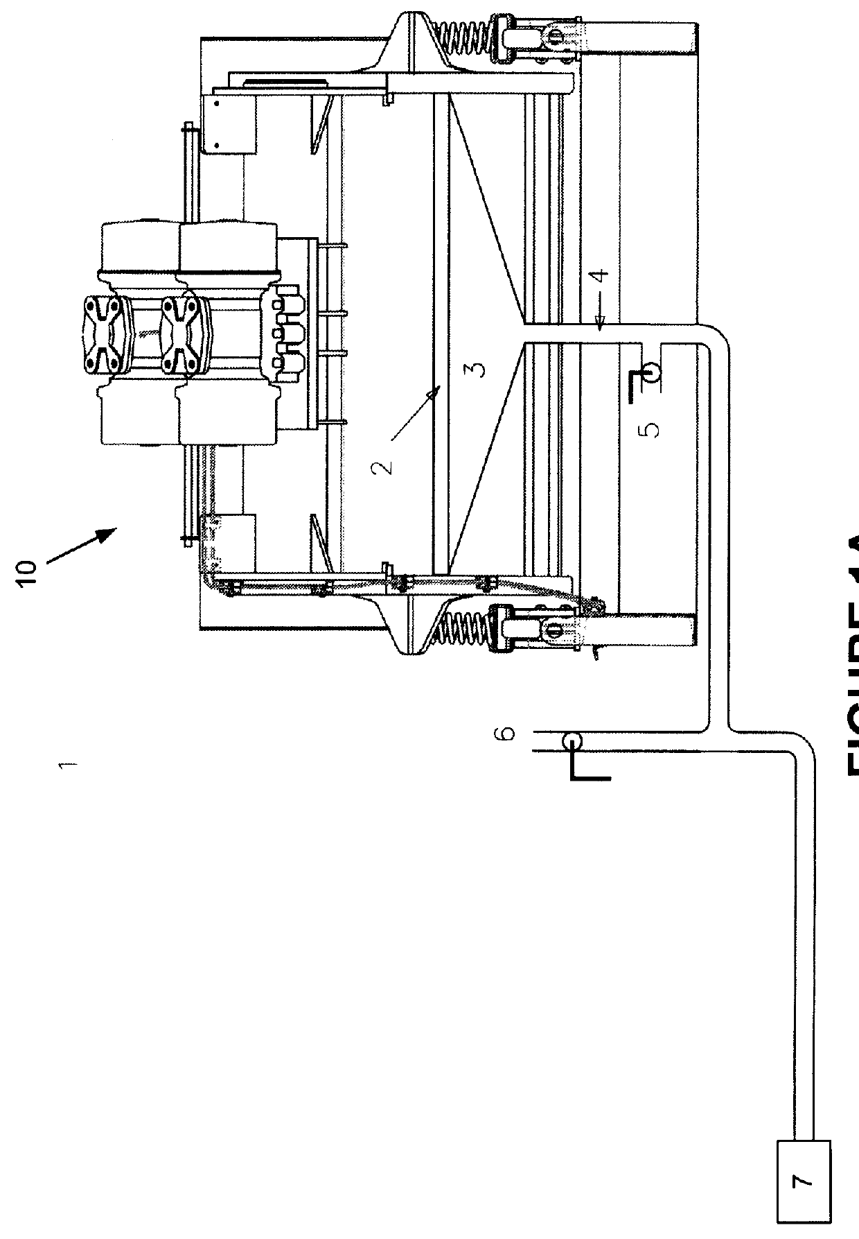
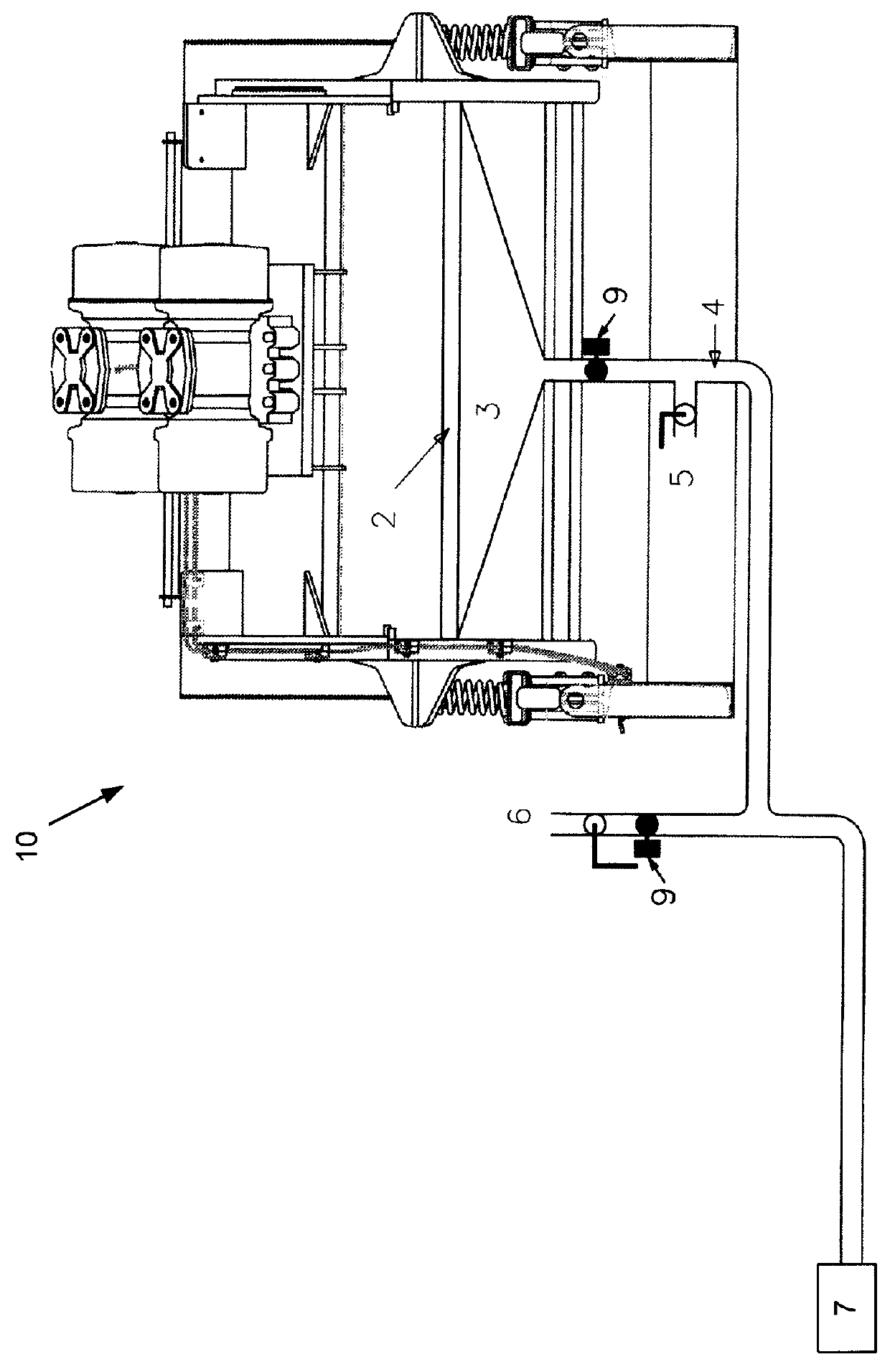
[0050]With reference to the figures, systems, apparatus and methods of controlling the quality and quantity of recovered drilling fluid from a shaker are described.

[0051]In a first embodiment as shown in FIG. 1, a drill cuttings / drill fluid shaker 10 is shown configured to a vacuum system 7. As described in Applicant's co-pending applications, the vacuum system 7 includes a fluid / air separator that enables the separation of fluid and air. The shaker includes a screen bed 2 supporting a number of shaker screens along the shaker bed. The shaker includes a vacuum manifold 3 operatively attached to at least one of the shaker screens or a portion of one of the shaker screens through the shaker bed. The vacuum manifold vibrates with the shaker bed and includes vacuum lines 4 that are connected to a vacuum pump system 7. The vacuum pump system can be operated to draw air through each manifold and each screen or a portion of one screen as drill cuttings and drill fluid are passed over one o...


PUM

PropertyMeasurementUnit
particle sizeaaaaaaaaaa
widthaaaaaaaaaa
widthaaaaaaaaaa

Abstract

The invention relates to improvements in vacuum shakers and more specifically to the integration of multiple shaker units to a common vacuum pump system, to apparatus for controlling the airflow through shaker screens, optimization of slurry transport, and to methods of separating drilling fluid from drill cuttings.

Description

FIELD OF THE INVENTION[0001]The invention relates to improvements in vacuum shakers and more specifically to the integration of multiple shaker units to a common vacuum pump system, to apparatus for controlling the airflow through shaker screens, optimization of slurry transport, and to methods of separating drilling fluid from drill cuttings.BACKGROUND OF THE INVENTION[0002]Screening machines to enhance the separation of solids and liquids have been used in various industries including the mining and oil industries for many years. As is well known, a screening machine typically includes a screen bed over which a solution containing fluids and solids is passed and then subjected to various separation forces including gravity and shaking. Each screen separation apparatus will utilize different types and sizes of screens to enable separation of different fluids / solids. In addition, the use of vacuum systems to improve separation within screening systems has also been implemented inclu...

Claims


Application Information

Patent Timeline
Patent Type & Authority Applications(United States)
IPC IPC(8): E21B21/06B01D33/03B01D33/80
CPCE21B21/065B01D33/804B01D33/03B07B1/28B07B1/46B07B4/08B07B13/16
Inventor POMERLEAU, DANIEL GUYHICKS, ANDREW
Owner FP MARANGONI INC
Why Eureka
Try Eureka