Centrifugal pump

Active Publication Date: 2016-02-04
HONDA MOTOR CO LTD
View PDF3 Cites 0 Cited by
  • Summary
  • Abstract
  • Description
  • Claims
  • Application Information

AI Technical Summary

Benefits of technology

[0015]By contrast, the straight peripheral edge section provided on the upstream side allows entry of the prime fluid from the straight peripheral edge section into the internal space of the flow-channel recessed portion uniformly over the width thereof. The prime fluid can thus be introduced from the opening into the internal space of the flow-channel recessed portion in an appropriate manner, and the introduced prime fluid can properly generate a vortex flow within the internal space of the flow-channel recessed portion.
[0016]Preferably, the flow-channel recessed portion has a part formed to protrude from the volute internal flow channel in a radial outward direction of the impeller. With this arrangement, the flow-channel recessed portion includes a first part (hereinafter referred to as “an inner flow-channel recess part”) corresponding in position to the volute internal flow channel, and a second part (hereinafter referred to as “an outer flow-channel recessed part”) arranged to protrude from the volute internal flow channel in the radial outward direction of the impeller. The prime fluid, as it flows along the volute internal flow channel, is subjected to a centrifugal force. The prime fluid introduced in an internal space of the inner flow-channel recessed part is subsequently introduced in the form of a vortex flow into an internal space of the outer flow-channel recessed part by the effect of the centrifugal force. Generation of the vortex flow by the prime fluid can be promoted, which will further promote generation of air babbles.
[0017]In one preferred form of the invention, the number of the flow-channe

Problems solved by technology

Under these circumstances, the degree of freedom in designing the shape of the vanes' distal ends is considerably low, and sufficient el

Method used


Image

  • Centrifugal pump
  • Centrifugal pump
  • Centrifugal pump

Examples


Embodiment Construction

[0035]A certain preferred structural embodiment of the present invention will be described in greater details below, by way of example only, with reference to the accompanying sheets of drawings.

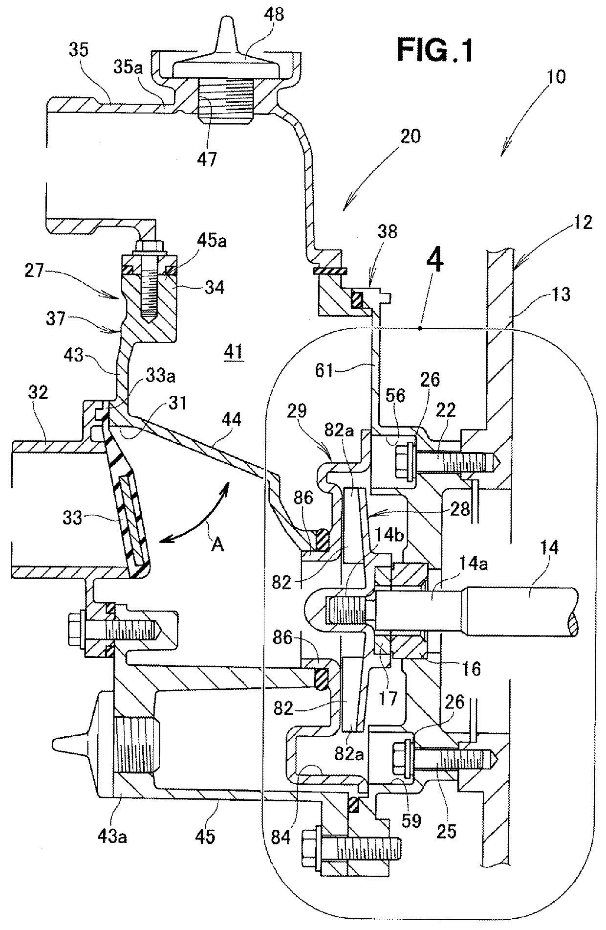
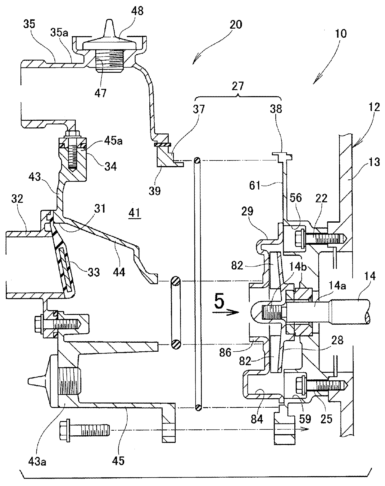
[0036]As shown in FIG. 1, a centrifugal pump unit 10 generally comprises a base (not shown) supporting the centrifugal pump unit 10, an engine 12 including a cylinder block 13 mounted on the base, and a centrifugal pump 20 provided on the cylinder block 13 of the engine 12.

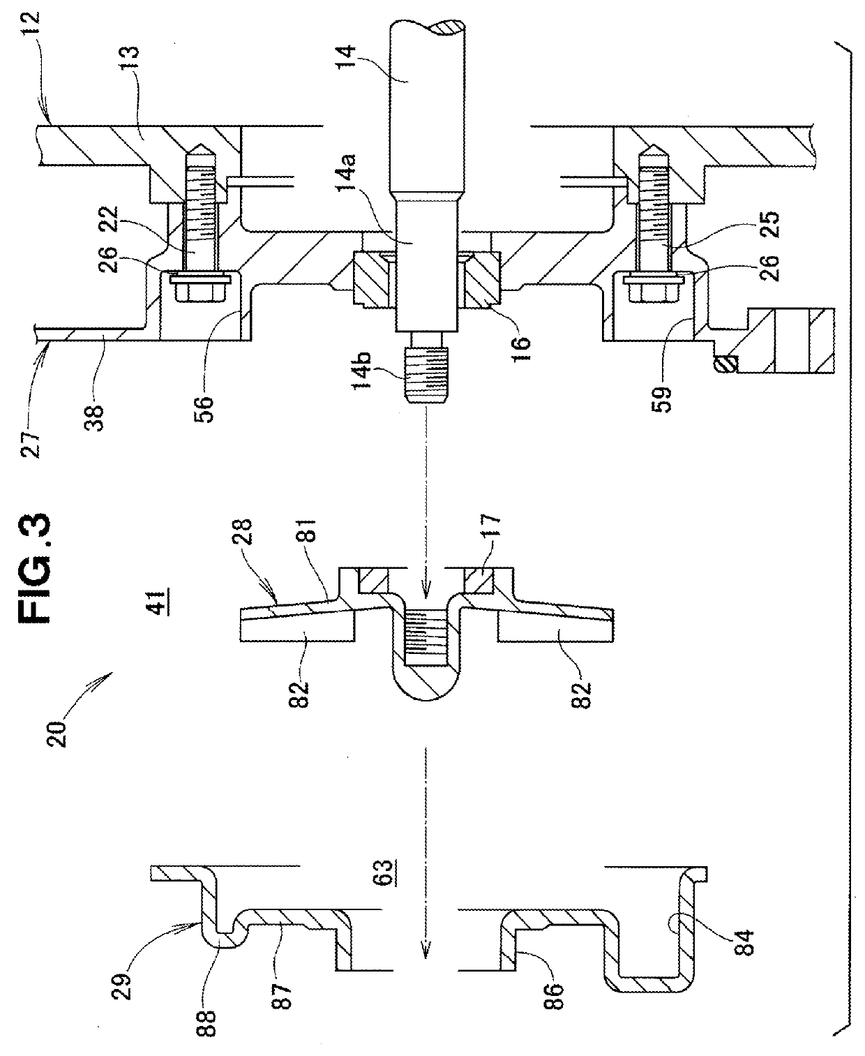
[0037]The engine 12 includes the cylinder block 13 mounted on the base, and a crankshaft (output shaft) 14 rotatably supported inside the cylinder block 13. The centrifugal pump 20 has a case member 27 (especially, a partition member 38 of the case member 27) mounted to the cylinder block 13 by first to fourth bolts 22-25 (the second and third bolts 23, 24 being shown in FIG. 5). A sealing washer 26 is disposed between each of the bolts 22-25 and the partition member 38 (especially, a volute support wall 61 of the partitio...


PUM


Abstract

A centrifugal pump includes an impeller rotatably disposed in a volute case for forcing a fluid to flow along a volute internal flow channel formed in the volute case, and first to fourth flow-channel recessed portions opening to the volute internal flow channel. The first and fourth flow-channel recessed portions are formed so as to be recessed in a direction substantially orthogonal to a direction of flow of the fluid. In a self-priming operation, the fluid is introduced into the first and fourth recessed portions whereupon the prime fluid is stirred within internal spaces of the first and second flow-channel recessed portions.

Description

FIELD OF THE INVENTION[0001]The present invention relates to a centrifugal pump configured to force a fluid to flow along a volute internal flow channel upon rotation of an impeller disposed in a volute case.BACKGROUND OF THE INVENTION[0002]Centrifugal pumps generally include a volute provided inside a casing, and an impeller provided on a rotating shaft projecting into the volute. The impeller has a hub mounted on the rotating shaft and a plurality of vanes provided on the hub. The impeller is disposed inside the volute. When the centrifugal pump is to be driven, a self-priming operation is performed to create a negative pressure inside the volute to thereby introduce a fluid, such as water, into the volute by the effect of the negative pressure.[0003]By thus introducing the fluid via the self-priming operation, a steady operation becomes possible. In the steady operation, the fluid is first sucked into the volute, then guided outside the volute (i.e., inside the casing) by the eff...

Claims


Application Information

Patent Timeline
IPC IPC(8): F04D29/42
CPCF04D29/4273F04D29/426F04D7/04F04D9/02
Inventor TSURUDA, KOUKIAKIYAMA, MASAHIROOKABE, KAKU
Owner HONDA MOTOR CO LTD
Why Eureka
Try Eureka