3D ultrasound imaging system

a technology of ultrasound imaging and ultrasound, applied in the field of three-dimensional ultrasound imaging, can solve the problems of requiring a lot of time, and requiring a lot of time, and achieves the effect of less scans and relatively easy operation of the presented system

Active Publication Date: 2016-02-11
KONINKLJIJKE PHILIPS NV
View PDF5 Cites 22 Cited by
  • Summary
  • Abstract
  • Description
  • Claims
  • Application Information

AI Technical Summary

Benefits of technology

[0007]It is an object of the present invention to provide an improved ultrasound imaging system, which allows a quicker, more comfortable and more reliable analysis of an anatomical object, e.g. of the human heart. It is furthermore an object of the present invention to provide a corresponding method and a computer program for implementing such method.
[0031]In other words, the generated 2D slices may be simultaneously presented on the display. This allows a doctor an easy comparison of the different standard views.
[0038]However, it has been shown that a lot less scans have to be performed in contrast to manually acquiring the 2D standard views with a 2D ultrasound scanner. Two or three 3D ultrasound scans of the human heart may, for example, already be enough in order to generate all 20 2D TEE standard views. Since the system itself selects the best generated 2D slice for each 2D standard view, the operation of the presented system is fairly easy. The user so to say only has to acquire enough 3D ultrasound scans until a “green light” is received for each standard view. This may even be done by the user in a trial and error manner without having to follow the usual elaborated protocols for acquiring the predefined standard views.

Problems solved by technology

This is a tedious and long procedure, which may take about 20 to 30 minutes.
The whole TEE procedure is quite uncomfortable for the patient.
Moreover, this process is relatively error-prone.

Method used


Image

  • 3D ultrasound imaging system
  • 3D ultrasound imaging system
  • 3D ultrasound imaging system

Examples


Embodiment Construction

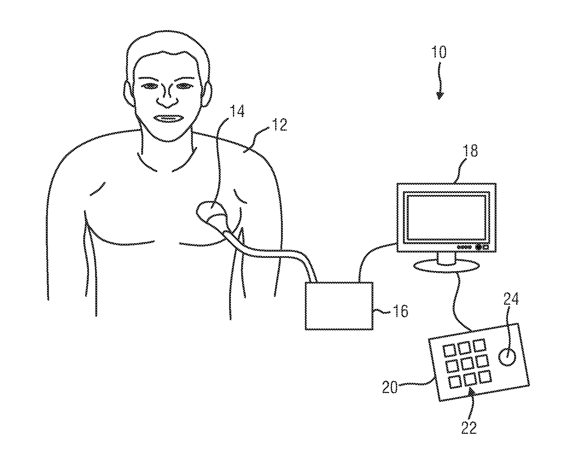
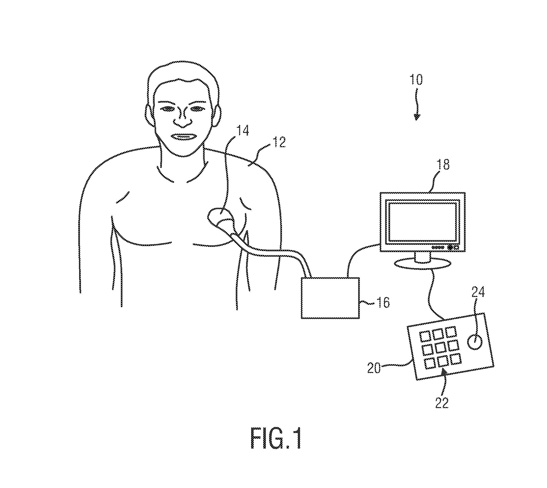
[0064]FIG. 1 shows a schematic illustration of an ultrasound system 10 according to an embodiment, in particular a medical three-dimensional (3D) ultrasound imaging system. The ultrasound imaging system 10 is applied to inspect a volume of an anatomical site, in particular an anatomical site of a patient 12. The ultrasound system comprises an ultrasound probe 14 having at least one transducer array having a multitude of transducer elements for transmitting and / or receiving ultrasound waves. In one example, the transducer elements each can transmit ultrasound waves in form of at least one transmit impulse of a specific pulse duration, in particular a plurality of subsequent transmit pulses. The transducer elements are preferably arranged in a two-dimensional array, in particular for providing a multi-planar or three-dimensional image.

[0065]A particular example for a three-dimensional ultrasound system which may be applied for the current invention is the CX40 Compact Xtreme ultrasoun...


PUM


Abstract

The present invention relates to an ultrasound imaging system (10) comprising:—an image processor (34) configured to receive at least one set of volume data resulting from a three-dimensional ultrasound scan of a body (12) and to provide corresponding display data,—an anatomy detector (38) configured to detect a position and orientation of an anatomical object of interest within the at least one set of volume data,—a slice generator (40) for generating a plurality of two-dimensional slices from the at least one set of volume data, wherein said slice generator (40) is configured to define respective slice locations based on the results of the anatomy detector for the anatomical object of interest so as to obtain a set of two-dimensional standard views of the anatomical object of interest, wherein the slice generator (40) is further configured to define for each two-dimensional standard view which anatomical features of the anatomical object of interest are expected to be contained, and—an evaluation unit (42) for evaluating a quality factor for each of the generated plurality of two-dimensional slices by comparing each of the slices with the anatomical features expected for the respective two-dimensional standard view.

Description

FIELD OF THE INVENTION[0001]The present invention relates to three-dimensional ultrasound imaging. In particular, the present invention relates to the generation and evaluation of two-dimensional standard views from three-dimensional ultrasonic volume data. An exemplary technical application of the present invention is the generation of two-dimensional transesophageal echocardiography (TEE) images based on one or more obtained three-dimensional TEE scans.BACKGROUND OF THE INVENTION[0002]A transesophageal echocardiogram is an alternative way to perform an echocardiogram. A specialized probe containing an ultrasound transducer at its tip is passed into the patient's esophagus. This allows to record precise ultrasound images of different components of the human heart.[0003]For a full transesophageal echocardiography (TEE) examination 20 different 2D TEE views have to be acquired. These 2D TEE views are predefined views (e.g. ME four chamber, ME two chamber, TG basal SAX, . . . ), which...

Claims


Application Information

Patent Timeline
Patent Type & Authority Applications(United States)
IPC IPC(8): A61B8/08A61B8/00G06F17/30G06K9/52G06K9/62G06T7/00G06T7/60G06T15/00
CPCA61B8/523G06T2207/30168A61B8/0883A61B8/463G06T7/0014G06F17/3028G06K9/6201G06T7/004G06T7/0079G06T7/60G06K9/52G06T15/005G06T2207/10136G06T2207/30048A61B8/483A61B8/085A61B8/12A61B8/14G01S15/8993G06T7/70G06T7/10G06F16/51G06F18/22G06V10/42
Inventor WAECHTER-STEHLE, IRINAWEESE, JUERGEN
Owner KONINKLJIJKE PHILIPS NV
Why Eureka
Try Eureka