Positioning System

a positioning system and positioning slide technology, applied in the direction of manufacturing tools, mechanical equipment, gearing, etc., can solve the problem of relative small positioning area of the positioning slide, and achieve the effect of simple structure and large positioning area

Active Publication Date: 2016-02-11
FEYRER HAHN GMBH
View PDF4 Cites 29 Cited by
  • Summary
  • Abstract
  • Description
  • Claims
  • Application Information

AI Technical Summary

Benefits of technology

[0004]The invention is based on the problem of providing measures which allow for a large positioning area of the positioning slide while providing a simple structure combined with small dimensions of the drive gears.
[0007]The positioning slide can be displaced in the x-axis direction by means of the driven rotation of an x-drive gear and the resulting interaction between the drive toothing of the x-drive gear and the currently assigned driven teeth of the tooth matrix, wherein those driven teeth of the tooth matrix which are simultaneously in engagement with the drive toothing of the y-drive gear are guided for linear displacement in the x-axis direction by its drive toothing and slide along in the drive toothing of the y-drive gear. The reverse comparably occurs at a driven rotation of a y-drive gear. By means of a matching driven rotation of at least one x-drive gear in engagement with the driven toothing structure and a y-drive gear likewise in engagement with the driven toothing structure, the positioning slide can be displaced in the positioning plane in any desired direction of movement and at a variable speed. The possibility of the interaction of the driven teeth with both the at least one x-drive gear and the at least one y-drive gear facilitates the implementation of a relatively large positioning area of the positioning slide together with compact dimensions of the drive gears. It is particularly advantageous that the base area of the slide support can be used to optimum advantage in the positioning movement of the positioning slide; there is even the possibility of an arrangement in which the positioning slide projects beyond the edges of the slide support.
[0009]As indicated above, it is advantageous if all of the driven teeth of the tooth matrix are capable of coming into tooth engagement with at least one x-drive gear and at least one y-drive gear at a time interval in the positioning movement of the positioning slide.
[0024]A modular structure of the slide support is considered to be particularly advantageous. Such a modular slide support comprises a plurality of support modules which can be or are lined up in a modular fashion in the x-axis direction and / or in the y-axis direction to form the slide support. Each of these support modules has at least one and preferably precisely one x-drive gear and at least one and preferably precisely one y-drive gear, each with associated drive means. Preferably, fastening means are provided for securing the lined-up support modules relative to one another; these fastening means may for example be screw fastening systems or latching systems. Together, the support modules form a module matrix representing the slide support. The modular structure facilitates by very simple means the provision of slide supports with different surface dimensions and / or different external contours for meeting application-specific requirements.
[0026]All support modules of the slide support can be or are expediently interconnected electrically and / or fluidically and / or optically in order to greatly simplify the transmission of energy and / or data and / or signals required for their operation. Each support module can be provided with plugging means or other preferably releasable connecting means which facilitate a simple interconnection when assembling the support modules.

Problems solved by technology

One disadvantage of the known positioning system is a relatively small positioning area of the positioning slide.

Method used


Image

  • Positioning System
  • Positioning System
  • Positioning System

Examples


Embodiment Construction

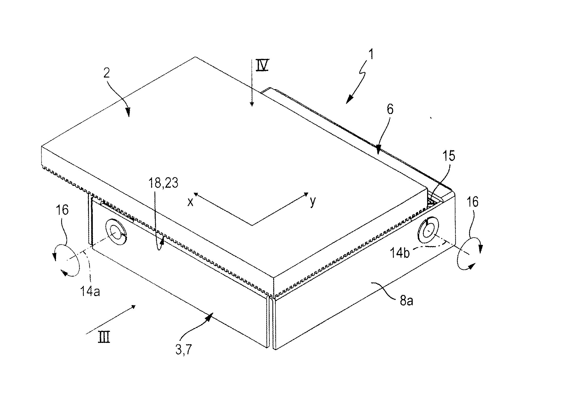
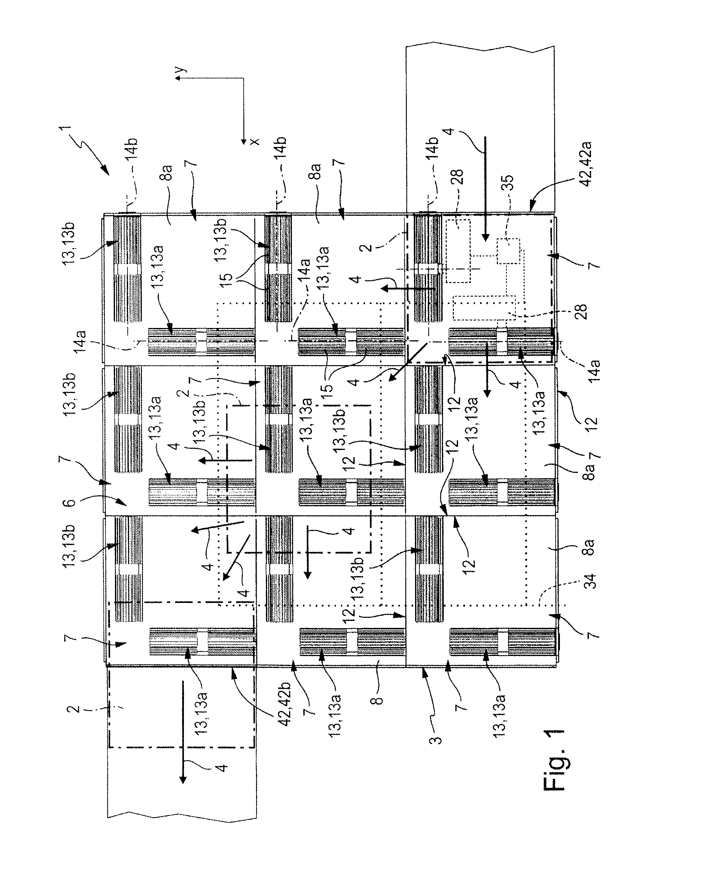
[0040]With reference to FIGS. 2 to 8, is should be said that the illustrated module can also represent an independent positioning system in which the whole of the slide support consists of a single support module which is not necessarily designed for lining up with further support modules. The whole slide support of the positioning system can in this case be represented by a single support module.

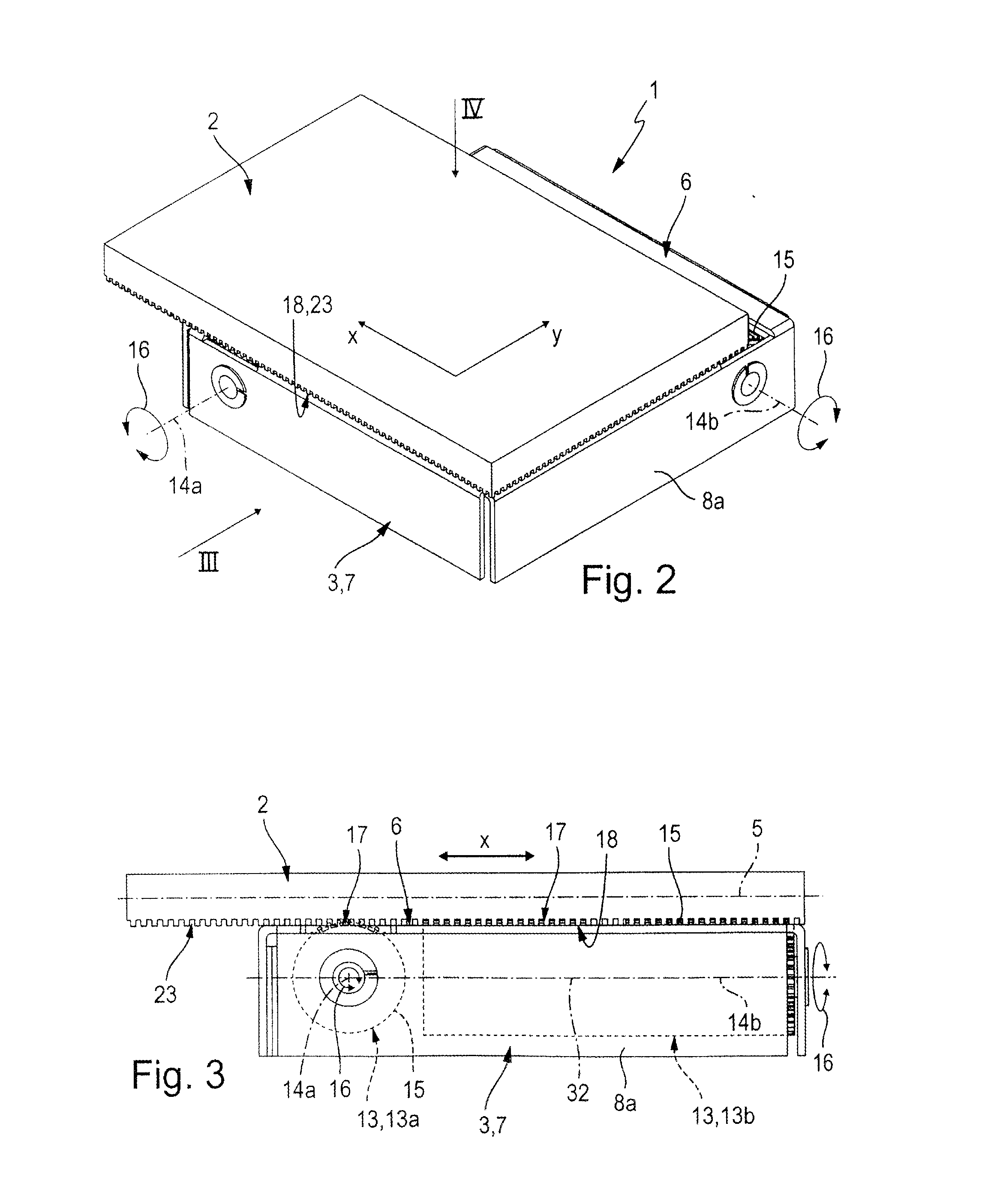
[0041]The positioning system identified as a whole by the reference number 1 comprises at least one positioning slide 2, which is mounted on a slide support 3 representing the base of the positioning system 1 and capable of being variably displaced and positioned relative to the slide support 3 while performing a positioning movement 4 illustrated by arrows.

[0042]The positioning plane 5 is defined by a Cartesian x-y coordinate system having an x-axis and a y-axis perpendicular to the former. In the following description, the direction of the x-axis will be described as the x-axis direction ...


PUM


Abstract

A positioning system includes a slide support, on which is mounted a positioning slide, which can be driven to perform a positioning movement in a positioning plane with the aid of drive gears of the slide support, wherein the positioning plane is defined by a Cartesian x-y coordinate system. The drive gears are represented by at least one x-drive gear, which can cause a positioning movement in the x-axis direction, and at least one y-drive gear, which can cause a positioning movement in the y-axis direction. The drive gears are in engagement with a driven toothing structure of the positioning slide, which includes a plurality of driven teeth distributed in a punctiform arrangement in a regular two-dimensional tooth matrix. Although the drive gears are short, the positioning system facilitates a traverse of the positioning slide within a large positioning area.

Description

BACKGROUND OF THE INVENTION[0001]The invention relates to a positioning system comprising at least one positioning slide which is variably traversable and positionable relative to a slide support of the positioning system while performing a positioning movement in a positioning plane defined by a Cartesian x-y coordinate system, wherein the slide support comprises at least one y-drive gear which can be driven by drive means of the positioning system to perform a drive rotary movement about an axis of rotation parallel to the x-axis of the coordinate system and at least one x-drive gear which can be driven by drive means to perform a drive rotary movement about an axis of rotation parallel to the y-axis of the coordinate system, wherein each y-drive gear and each x-drive gear has a drive toothing at its outer circumference and wherein the positioning slide has a driven toothing structure with which it is simultaneously in tooth engagement with the drive toothing of at least one x-dri...

Claims


Application Information

Patent Timeline
Patent Type & Authority Applications(United States)
IPC IPC(8): F16H19/04B23Q3/18
CPCF16H19/04B23Q3/18B23Q1/621B23Q5/385
Inventor FEYRER, THOMAS
Owner FEYRER HAHN GMBH
Why Eureka
Try Eureka