
Flange catching, aligning and closing tool

a tool and spool technology, applied in the field of flange catching, aligning and closing tools, can solve the problems of poor visibility, many hours of completion, and significant ordeal in the completion of spool tie-in, and achieve the effect of convenient insertion

Inactive Publication Date: 2016-02-11
OSPREY SUBSEA TECHN SOLUTIONS OSTS
View PDF9 Cites 21 Cited by
  • Summary
  • Abstract
  • Description
  • Claims
  • Application Information

AI Technical Summary

Benefits of technology

The patent is about a device that allows for smooth movement and accurate positioning of a drift pin when inserting it into a matching bolt hole. The device includes a cylinder with a hollow space and a slide assembly that is mounted on the outside of the cylinder. The slide assembly is controlled by a guide slot in the cylinder, which allows for smooth movement. The guide slot has an enlarged portion that allows for a degree of lateral movement, making it easier to insert the drift pin into the bolt hole. The technical effect of this device is to facilitate the assembly process and improve the accuracy of the drift pin insertion.

Problems solved by technology

Achieving successful tie-in and connection of subsea pipelines and flow-lines is a delicate and important element of subsea oil and gas field development.
This makes the task of completing a spool tie-in a significant ordeal, taking many hours to complete and often with only one diver working alone at any given time.
The whole operation is undertaken in-situ (below water), often using a diver to provide manual labour, and frequently with poor visibility.

Method used


Image

  • Flange catching, aligning and closing tool
  • Flange catching, aligning and closing tool
  • Flange catching, aligning and closing tool

Examples


first embodiment

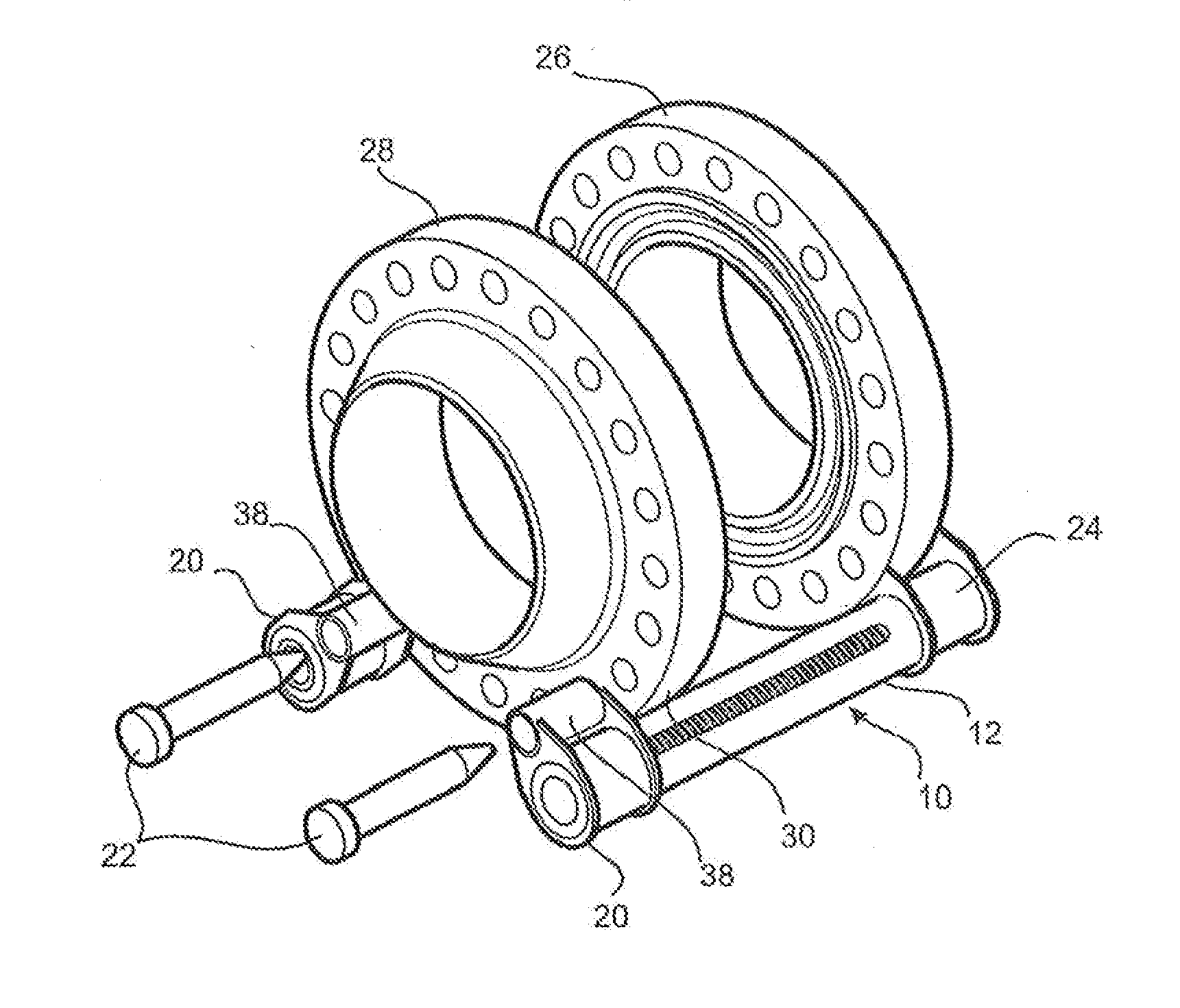
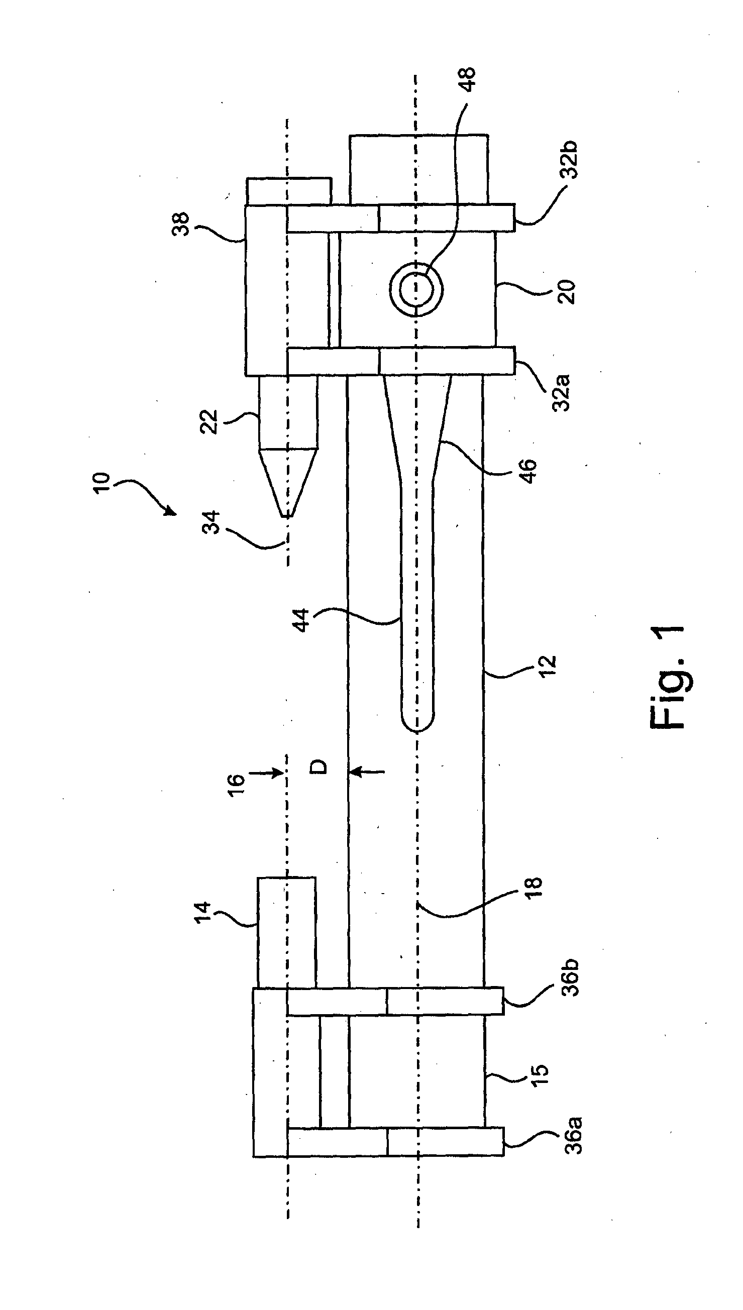
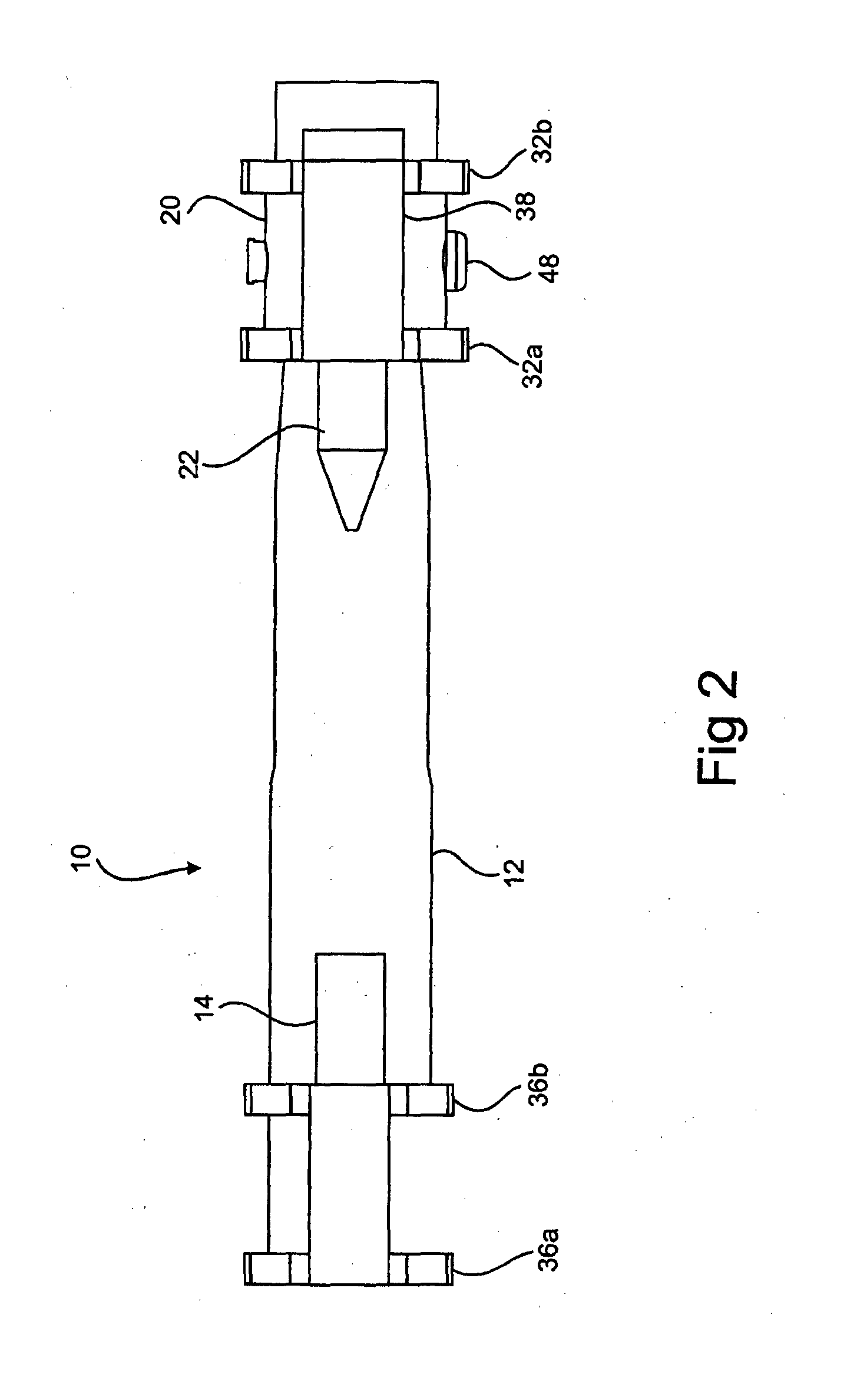
[0037]a tool 10 for catching, aligning and closing flanges in accordance with the invention, as illustrated in FIGS. 1 to 4, comprises an elongate support member 12 with a locating pin 14 mounted adjacent a first end 15 of the support member 12. The locating pin 14 is mounted with its longitudinal axis 16 substantially parallel to a longitudinal axis 18 of the support member 12.

[0038]A slide assembly 20 is slidably mounted on the support member 12 and has a movable podger bar or drift pin 22 provided in connection therewith. In use, when the locating pin 14 is located in a bolt hole 24 on a first flange 26 (see FIG. 4), a second flange 28 can be brought into partial alignment with the first flange 26 by resting on the support member 12. The drift pin 22 can then be inserted in a matching bolt hole 30 in the second flange 28 to bring the two flanges into full alignment. A preferred method of catching, aligning and closing flanges in accordance with the invention will be described in ...

second embodiment

[0053]FIGS. 9 and 10 illustrate a tool 42 for catching, aligning and closing flanges according to the present invention. The tool 42 is similar to the tool 10 of FIGS. 7 and 8 and therefore the similar parts are identified with same reference numerals and will not be described again in detail. The tool 42 is also provided with a second kind of actuator 40 in the form of a hydraulic ram 70 with a piston 74, however in this case the actuator 40 is configured in a push configuration. The actuator 40 is shown in section view in FIG. 10. The hydraulic ram 70 is mounted on the opposite end of cylindrical support member 12, and a shaft 72 of piston 74 extends into the cylinder 12 to the slide assembly 20. The guide pin 48, on the slide assembly 20, passes through a swivel 76 (see FIG. 9(e)) on the end of the piston shaft 72 so as to transfer the forces to the slide assembly 20 for linear motion. With this arrangement, the hydraulic ram 70 can be used to push the flanges together to such a ...


PUM


Abstract

A flange catching, aligning and closing tool (10) designed to facilitate the tie-in of spools and other similar mechanical assemblies that utilise a bolted flange for installation, for example, in subsea pipelines. The tool (10) has an elongate support member (12) having a locating pin (14) mounted adjacent one end with its longitudinal axis (16) substantially parallel to a longitudinal axis (18) of the support member (12). A slide assembly (20) is slidably mounted on the support member (12) and has a movable drift pin (22) provided in connection therewith. In use, when the locating pin (14) is located in a bolt hole on a first flange, a second flange can be brought into partial alignment with the first flange by engaging with the support member (12), and the drift pin (22) can be inserted in a matching bolt hole in the second flange to bring the two flanges into full alignment.

Description

FIELD OF THE INVENTION[0001]The present invention relates to a tool and method for catching, aligning and closing the flanges on a spool or similar mechanical assembly that utilises a bolted flange for installation and relates particularly, though not exclusively, to such a tool and method used for subsea spool tie-ins.BACKGROUND TO THE INVENTION[0002]Subsea pipelines and flow-lines are used for the transportation of crude oil and gas from subsea wells, other subsea structures, and off-shore processing facilities, as well as for re-injecting water and gas into subsea reservoirs. Achieving successful tie-in and connection of subsea pipelines and flow-lines is a delicate and important element of subsea oil and gas field development. Typically spools are used to effect the connection between the pipeline and a well head or other subsea structure.[0003]Spools can vary greatly in weight, diameter, length and geometry, from a small 2″×2 m straight spool to a 24″×50 m multi dogleg spool to...

Claims


Application Information

Patent Timeline
IPC IPC(8): B25B27/16E21B17/02F16L1/09F16L1/10F16L1/26
CPCB25B27/16F16L1/10E21B17/02F16L1/26F16L1/09E21B43/013F16L23/003
Inventor VOSS, ROY
Owner OSPREY SUBSEA TECHN SOLUTIONS OSTS
Learn More