

Sacrificial energy dissipation mechanism
- Summary
- Abstract
- Description
- Claims
- Application Information
AI Technical Summary
Benefits of technology
Problems solved by technology
Method used
Image

Examples
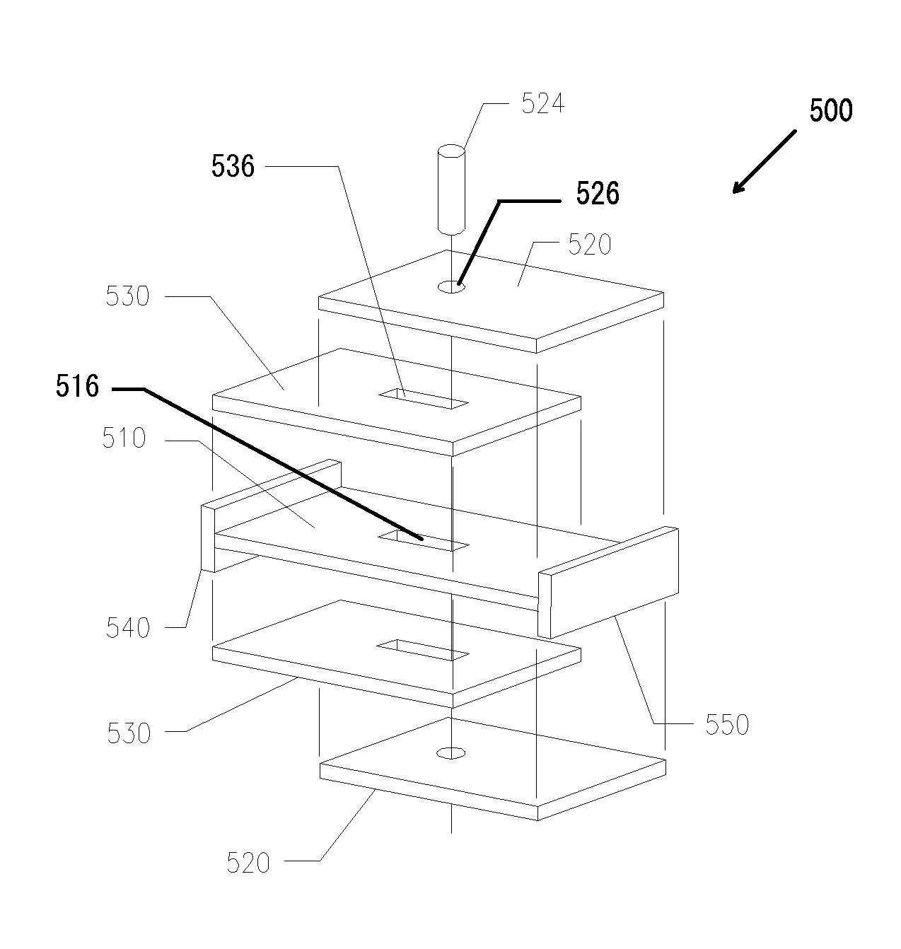
embodiment 500
[0042]The interlocks 120, 130, and 420, 520, or 530, depicted in and described with respect to the devices 100, 400, and 500 include a mechanism to provide contact between the interlock pairs when the device is placed into tension. This contact mechanism can take the form of a pair of flanges 124, 134, and 424, a slot 526 and stud 524 pair as depicted in FIG. 5's illustration of energy dissipation device embodiment 500.
[0043]FIG. 6 illustrates another embodiment of an energy dissipation device using interlocks which do not provide lateral restraint to the filament, instead using additional components to provide the lateral restraint to the filament. In particular, the energy dissipating device 600 includes a filament 610 extending between end-caps 640 and 640. At least one end-cap 640 includes filament bracing components 620 surrounding the filament 610 to provide lateral restraint to the filament 610 when the device 600 is in compression. In addition to the filament bracing compone...
embodiment 200
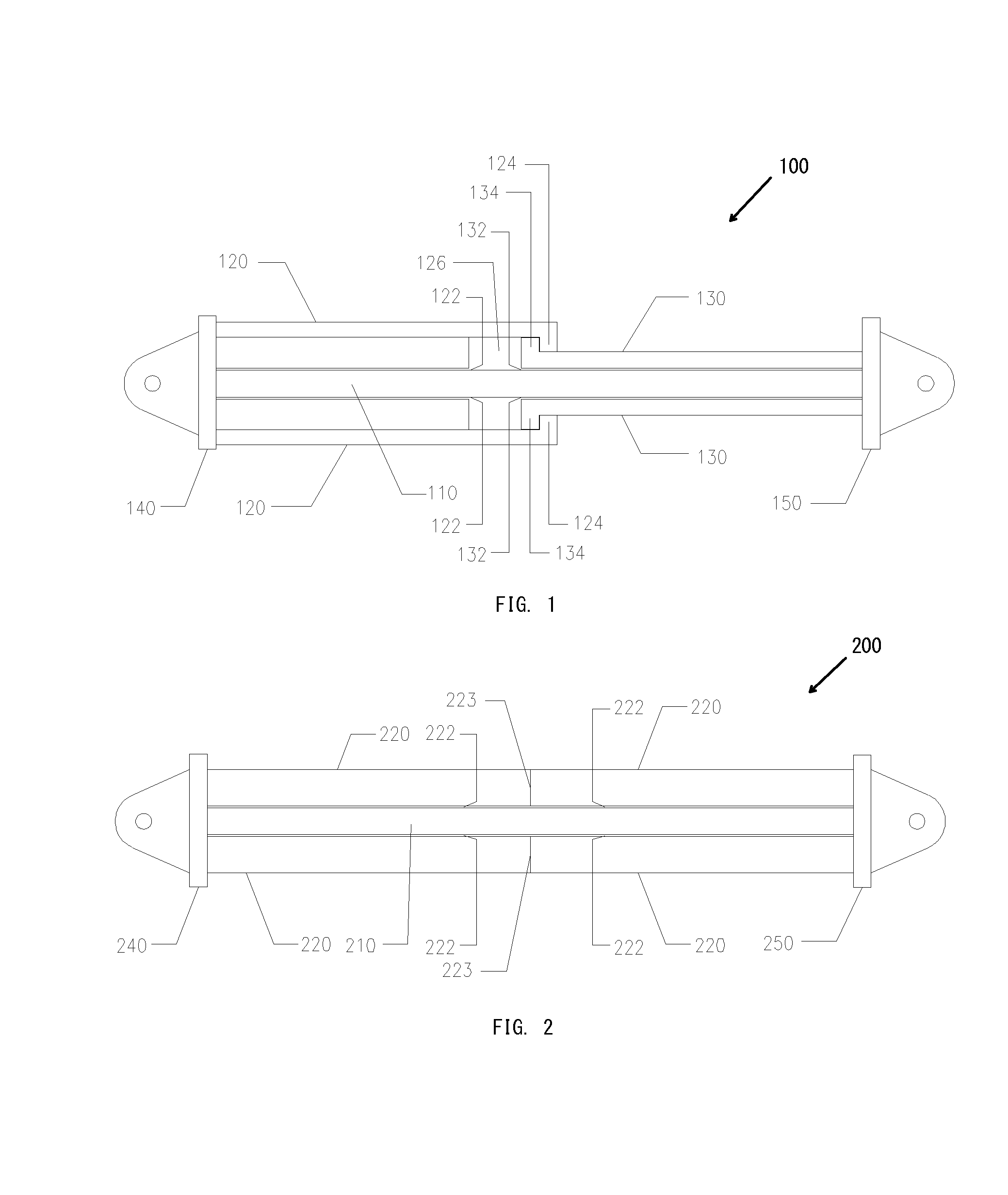
[0050]FIG. 2 illustrates a cross-sectional view of an energy dissipation device which is configured to be stronger and stiffer in compression than in tension. This device embodiment 200 includes a filament 210 extending through the receiving space 222 defined by the positions of interlocks 220. The interlocks 220 are configured such that they cannot overlap each other when the device is compressed. The facing end surfaces 223 of the interlocks 220 thus serve as contact surfaces which, when engaged with one another, constrain further lateral translation of the end-caps 240 and 250 towards one another. The filament 210 and interlocks 220 are connected at each end of the device to the end-caps 240 and 250 in a similar fashion as configuration 100.
[0051]The interlocks 220 will provide a continuous lateral restraint along the longitudinal axis of the filament 210, except when the device 200 has been tensioned and the interlocks 220 have separated. Note that the interlocks 220 may be cons...
PUM
 Abstract
Description
Claims
Application Information