Specimen measuring device and computer program product

a technology of measuring device and computer program, applied in the direction of optical radiation measurement, instruments, spectrometry/spectrophotometry/monochromator, etc., can solve the problems of difficult to quantify texture, glittering feeling,

Active Publication Date: 2016-02-11
RICOH KK
View PDF14 Cites 24 Cited by
  • Summary
  • Abstract
  • Description
  • Claims
  • Application Information

AI Technical Summary

Problems solved by technology

In the case of the color measuring method defined in the ASTM standard, however, there was a problem in that a color measurement result is not identical to an evaluation by visual observation.
However, in the multi-angle color measuring method defined in the ASTM standard (E2539-12), it is difficult to quantify the texture such as the glittering feeling, the graininess, the orange peel, and the image clarity in a paint including a glittering material that looks a different color according to an observation angle.
Further, in the multi-angle color measuring method defined in the ASTM standard (E2539-12), since it was difficult to quantify the texture such as the glittering feeling, there was a problem in that it was difficult to quantify the quality of a paint including a glittering material that looks a different color according to an observation angle comprehensively.

Method used


Image

  • Specimen measuring device and computer program product
  • Specimen measuring device and computer program product
  • Specimen measuring device and computer program product

Examples


first embodiment

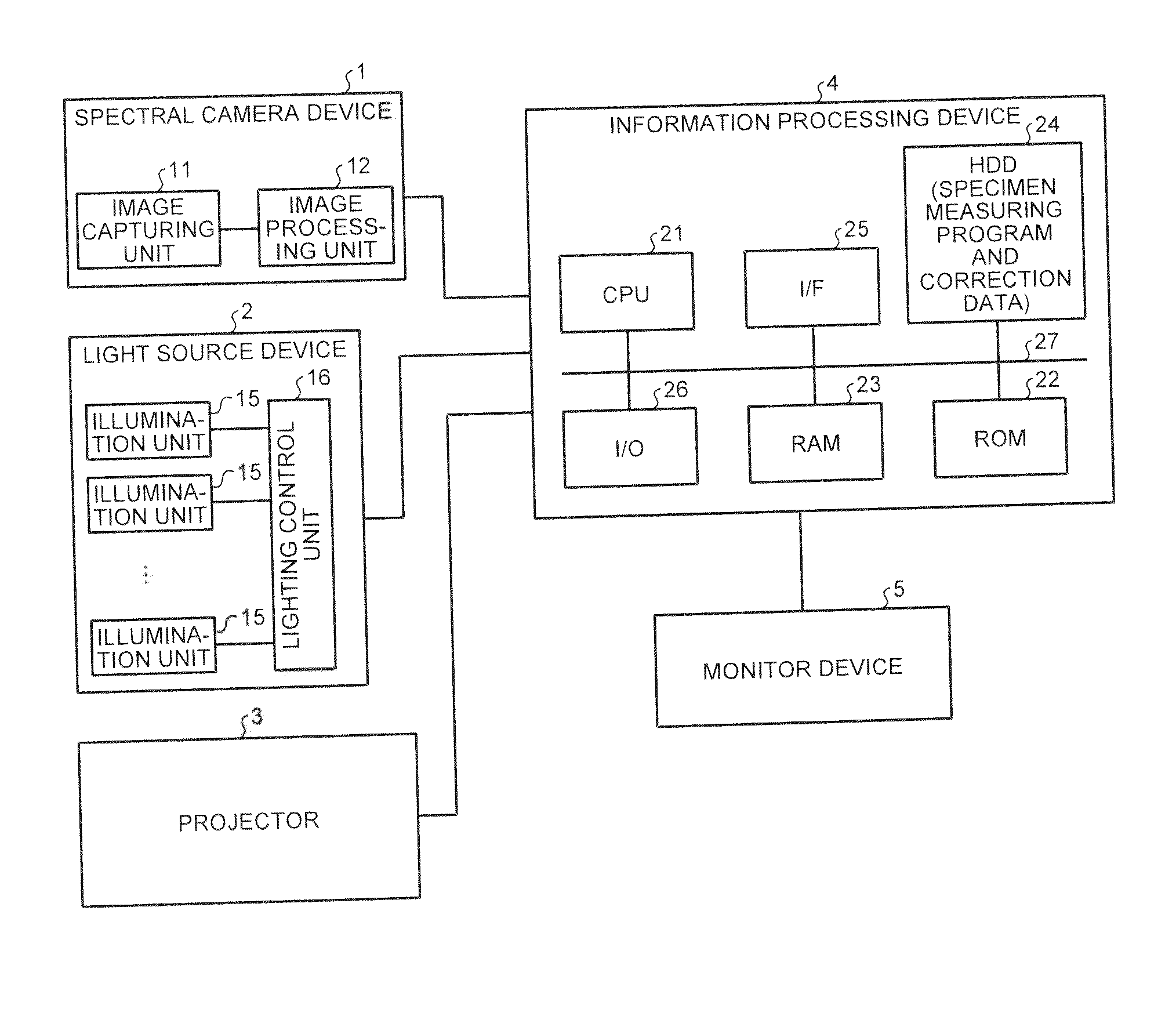
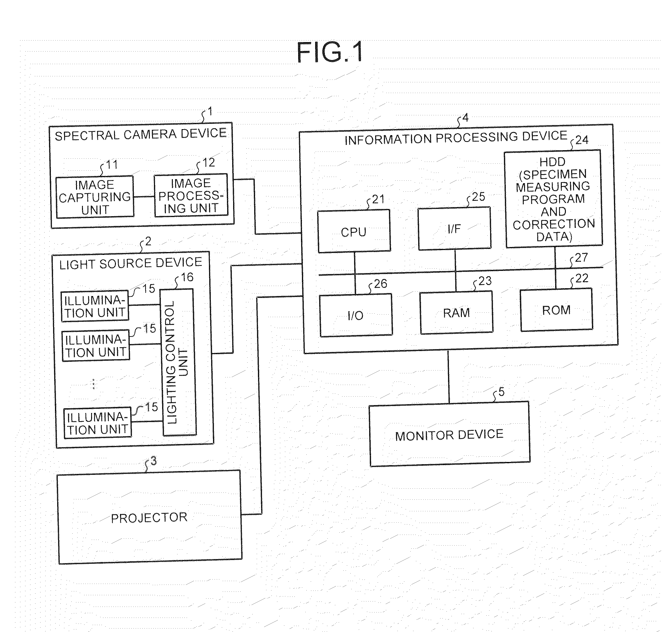
[0062]FIG. 1 is a block diagram illustrating a specimen measuring device according to a first embodiment. The specimen measuring device includes a spectral camera device 1, a light source device 2, a projector 3, an information processing device 4, and a monitor device 5 as illustrated in FIG. 1.

[0063]As will be described later, a multi-band camera device may be used as the spectral camera device 1. The multi-band camera device acquires spectral information according to the number of spectral filters for each micro lens through a spectral filter group inserted into a main lens and a micro lens array inserted between the main lens and the light receiving element as a spectral information acquiring unit that acquires 2D spectral information. Further, a hyper spectral camera device including one or more sets of filters and diffraction gratings (or prisms) may be used as the spectral camera device 1.

[0064]The spectral camera device 1 includes an image capturing unit 11 and an image proc...

second embodiment

[0164]Next, a specimen measuring device according to a second embodiment will be described. The specimen measuring device according to the first embodiment emits and captures an image of slit light 81 when the image clarity is measured.

[0165]On the other hand, the specimen measuring device according to the second embodiment controls the projector 3 such that the pattern projection control unit 33 projects a 2D white noise 82 including a spatial frequency of up to an image capturing limit spatial frequency of the spectral camera device 1 onto the specimen as illustrated in FIG. 31 when a timing to measure the image clarity comes. Further, as described above, the light source control unit 31 performs the lighting driving on the illumination units sequentially, and the image capturing control unit 32 performs the image capturing control on the spectral camera device 1 to capture an image of the white noise 82.

[0166]The white noise has the same strength at all frequencies when a Fourier...

third embodiment

[0167]Next, a specimen measuring device according to a third embodiment will be described. The specimen measuring device according to the third embodiment can perform measurement that is not influenced by the shape of the measurement target surface by correcting the optical geometrical condition of the 3D shape of each position of the specimen surface.

[0168]Specifically, the specimen measuring device according to the third embodiment acquires the slit light projected from the projector 3 or the 3D shape of each position of the specimen surface through a 3D information acquiring device 90 illustrated in FIG. 34. The measurement value calculating unit 36 calculates a normal line direction of each position of the specimen from the acquired 3D shape of each position of the specimen surface. Then, the measurement value calculating unit 36 corrects the calculated normal line direction of each position of the specimen and a regular reflection direction of light from the illumination unit b...


PUM


Abstract

A specimen measuring device includes: a light source device that irradiates a specimen surface of a specimen with illumination light from multiple illumination units at a plurality of illumination angles; a spectral camera device that is arranged above the specimen surface, spectrally separates reflected light from the specimen surface, and acquires 2D spectral information through a single image capturing operation; and a calculating unit that calculates deflection angle spectral information of the specimen surface used to measure a measurement value of a certain evaluation item of the specimen using a change in an optical geometrical condition of an illumination direction and an image capturing direction between pixels in an X axis direction and a Y axis direction of the spectral information.

Description

CROSS-REFERENCE TO RELATED APPLICATIONS[0001]The present application claims priority to and incorporates by reference the entire contents of Japanese Patent Application No. 2014-159917 filed in Japan on Aug. 5, 2014.BACKGROUND OF THE INVENTION[0002]1. Field of the Invention[0003]The present invention relates to a specimen measuring device and a computer program product.[0004]2. Description of the Related Art[0005]In these days, as an evaluation of a paint including a glittering material that looks a different color according to an observation angle such as a pearlescent color or a metallic color, a multi-angle color measuring method defined in an ASTM standard (E2539-12) has been known. ASTM stands for American Society for Testing and Materials. In the case of the color measuring method defined in the ASTM standard, however, there was a problem in that a color measurement result is not identical to an evaluation by visual observation.[0006]Japanese Patent Application Laid-open No. 2...

Claims


Application Information

Patent Timeline
Patent Type & Authority Applications(United States)
IPC IPC(8): G01B11/30G01J3/14G01J3/18
CPCG01B11/306G01J3/14G01J3/18G01B11/303G01J3/513G01J3/504G01N21/251G01N21/255G01N21/4738G01N21/4785G01N21/55G01N21/57G01N21/8422G01N2021/1776G01N2021/3177G01N2021/4711G01N2021/575G01N2201/0635G01J3/2823G01J3/465G01J3/0208
Inventor NAGAI, SHOMASUDA, KENSUKEMARUYAMA, GOYAMANAKA, YUJIKAMIJO, NAOHIROKAGITANI, KENJI
Owner RICOH KK
Why Eureka
Try Eureka