Timing synchronization circuit for wireless communication apparatus

a wireless communication apparatus and timing synchronization technology, applied in the field of wireless communication systems, can solve the problems of high probability of either a hold or a setup violation

Active Publication Date: 2016-02-11
NXP USA INC
View PDF2 Cites 22 Cited by
  • Summary
  • Abstract
  • Description
  • Claims
  • Application Information

AI Technical Summary

Problems solved by technology

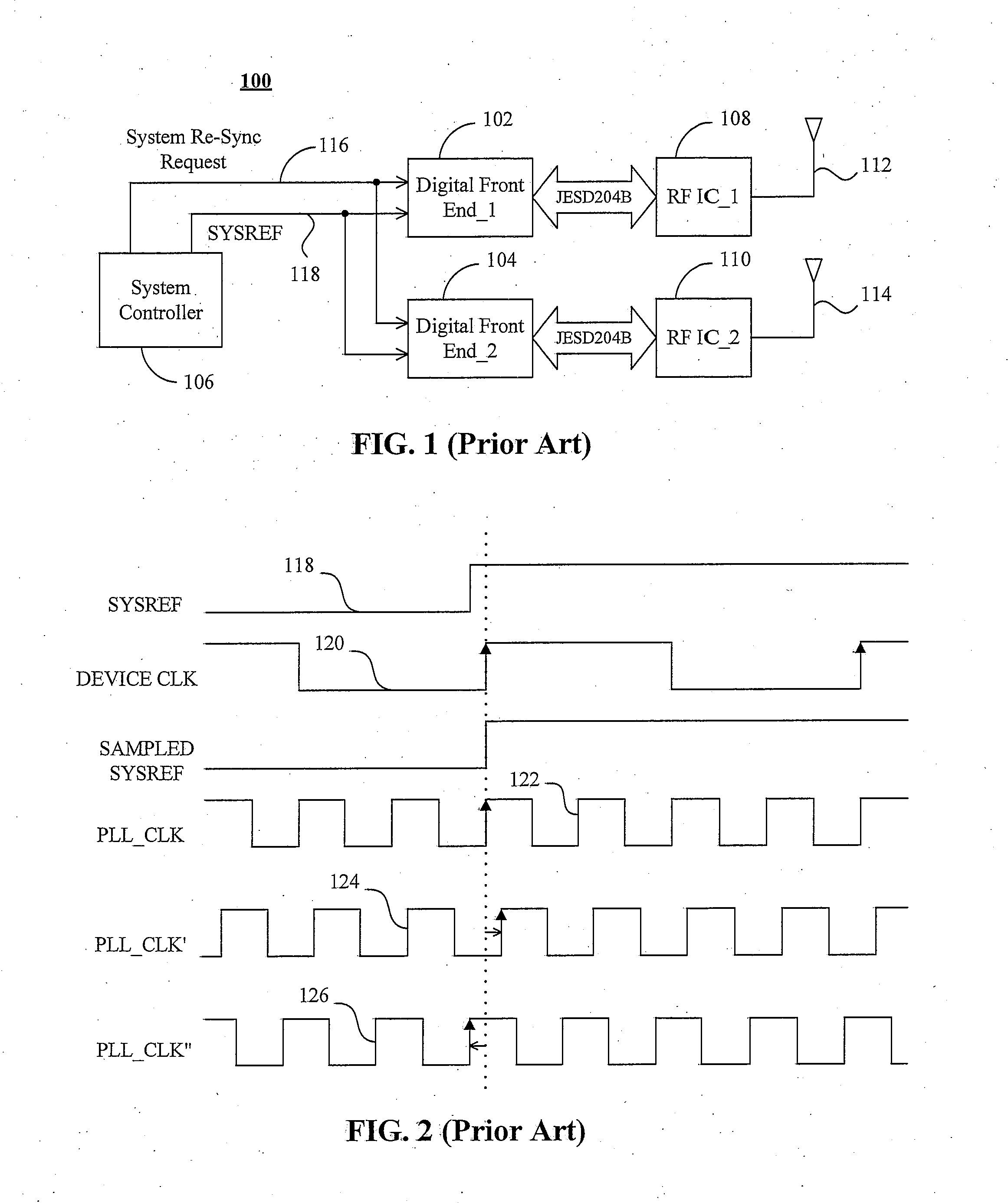
However, as shown in FIG. 2, PLL jitter moves the edge of the phase locked clock 122 either behind or ahead of the edge of an ideal phase locked clock PLL_CLK, as shown by PLL_CLK′124 and PLL_CLK″126, which results in a high probability of either a hold or setup violation.

Method used


Image

  • Timing synchronization circuit for wireless communication apparatus
  • Timing synchronization circuit for wireless communication apparatus
  • Timing synchronization circuit for wireless communication apparatus

Examples


Embodiment Construction

[0014]The detailed description set forth below in connection with the appended drawings is intended as a description of presently preferred embodiments of the invention, and is not intended to represent the only forms in which the present invention may be practised. It is to be understood that the same or equivalent functions may be accomplished by different embodiments that are intended to be encompassed within the spirit and scope of the invention. In the drawings, like numerals are used to indicate like elements throughout. Furthermore, the terms “comprises,”“comprising,” or any other variation thereof, are intended to cover a non-exclusive inclusion, such that module, circuit, device components, structures and method steps that have a list of elements or steps does not include only those elements but may include other elements or steps not expressly listed or inherent to such module, circuit, device components or steps. An element or step proceeded by “comprises . . . a” does no...


PUM


Abstract

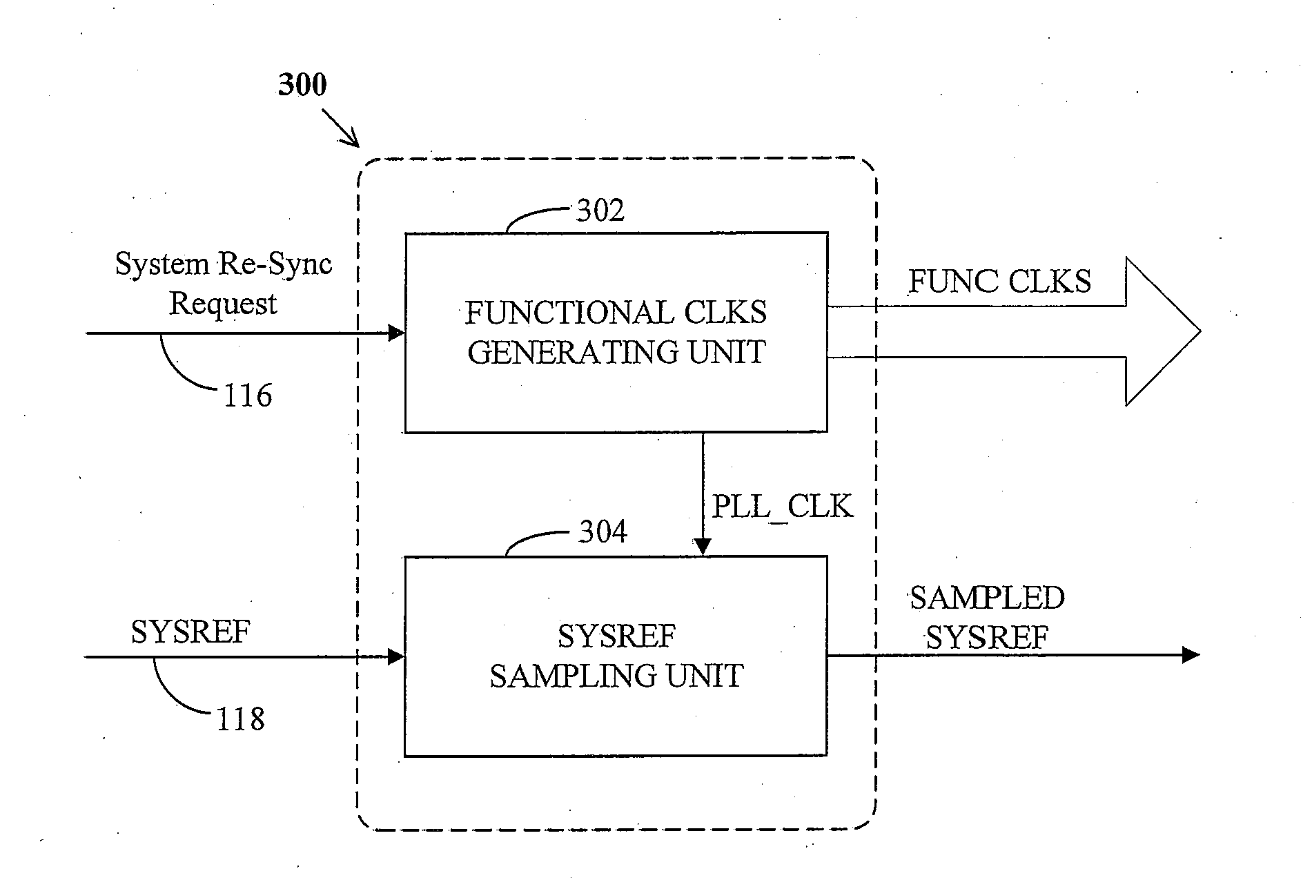
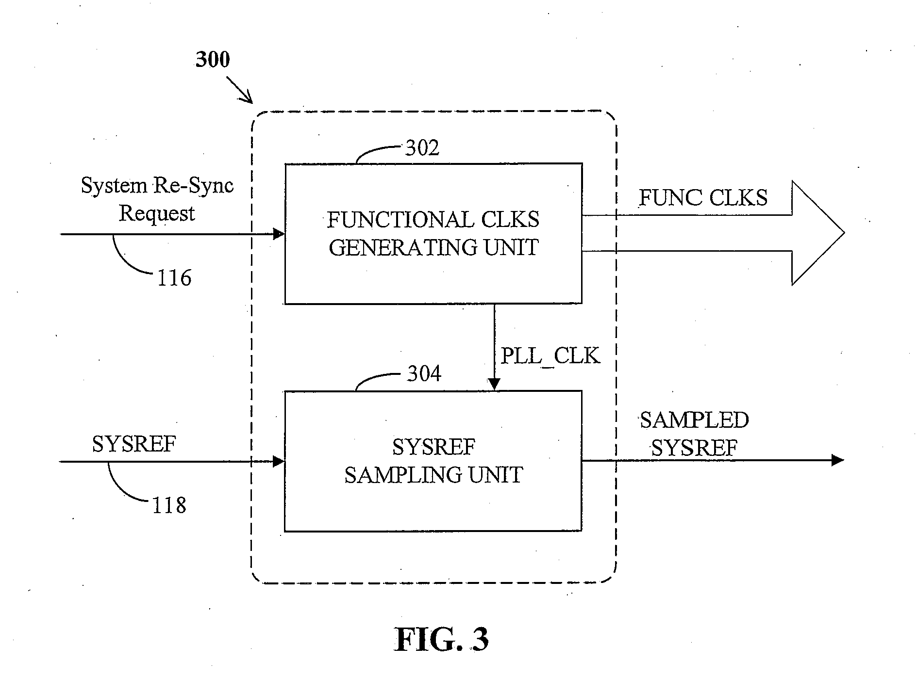
A transmission node includes a digital front-end device that provides functional clocks for JESD204B based data transmission. The front-end device includes a PLL for generating a phase locked clock based on a device clock of the front-end device, a clock dividing unit for generating the functional clocks by dividing the phase locked clock, a clock gating unit connected between the PLL and the clock dividing unit, and a system reference signal sampling unit for timing radio frame boundaries. The clock gating unit gates the phase locked clock to align the functional clocks with the device clock within a predetermined number of cycles of the phase locked clock, upon locking of the PLL or receipt of a system resynchronization request. The system reference signal sampling unit samples the system reference signal with zero-cycle latency between device clock and phase locked clock.

Description

BACKGROUND OF THE INVENTION[0001]The present invention relates to wireless communication systems and, more particularly, to a method of multichip synchronization in a remote radio head.[0002]FIG. 1 shows a topology of a multichip remote radio head (RRH) environment of a transmission node 100 in a wireless communication network. The transmission node 100 includes at least two digital front-end devices 102 and 104 controlled by a system controller 106. Each of the digital front-end devices 102 and 104 respectively communicates with one of radio frequency interface chips (RFICs) 108 and 110 using the JESD204B protocol, which is a serial protocol. A RFIC is a device that has an analog to digital converter (ADC), a digital to analog converter (DAC) and an interface to a radio frequency physical antenna (RF PA), such as antennas 112 and 114. The JESD204B protocol requires a plurality of functional clocks provided by the digital front-end devices 102 and 104 indicating different timing bou...

Claims


Application Information

Patent Timeline
Patent Type & Authority Applications(United States)
IPC IPC(8): G06F1/12G06F1/08
CPCG06F1/08G06F1/12G06F1/10H03J7/00H03L7/16H03L7/06H03L7/00H04B15/00
Inventor ALI, INAYATKAUSHIK, ARVINDPRAKASH, SACHINSINHA, ARINDAM
Owner NXP USA INC
Why Eureka
Try Eureka