Monitoring and control display system and method

a display system and display system technology, applied in the field of monitoring and control display system and method, can solve the problems of affecting the operation of the tractor, so as to achieve the effect of reducing the amount of effort, facilitating navigation, and avoiding undue delay

Active Publication Date: 2016-02-11
TOPCON POSITIONING SYST INC
View PDF3 Cites 63 Cited by
  • Summary
  • Abstract
  • Description
  • Claims
  • Application Information

AI Technical Summary

Benefits of technology

[0007]Moreover, the display is not merely an aggregation of the information provided in the multiple separate screens. Instead non-limiting embodiments of the present application include systems and techniques for presenting information in a manner that enables an operator to easily navigate from one function set to another without undue inconvenience.
[0008]A further feature of non-limiting embodiments of the present application is that it enables an operator to personalize all the above noted elements on a single screen in a flexible and user friendly configuration easily and with a minimum amount of effort.
[0009]A further aspect of non-limiting embodiments of the present application is that the user interface presents multiple functions on a single display screen without the user losing information portraying the machine's working area. Alternatively, if the operator wants the display to be as clutter free as possible, he / she can control the screen to bring up needed information, such as an alert or when an operating parameter is exceeded with a minimal sacrifice of a working area view.
[0010]As such, non-limiting embodiments of the present application provide a machine control display system and a display configuration methodology that enables an operator to efficiently and in a personalized manner see all aspects of the machine without confusion, without undue delay and without sacrificing a working view of the machine's operations.

Problems solved by technology

When an operator of a complex machine, such as a farm tractor needs to control multiple features and function of the device, that operator is often confronted with a technical overload.
The sheer quantity of consoles is not only difficult and confusing to use, but can also block the operator's critical view outside the tractor cab.
Instantaneous decision making also involves typical questions like “how do I change that parameter or address that problem?” or “how do I access the right information to change the parameter?” Often each display is too complicated or too inadequate to quickly address these questions.

Method used


Image

  • Monitoring and control display system and method
  • Monitoring and control display system and method
  • Monitoring and control display system and method

Examples


Embodiment Construction

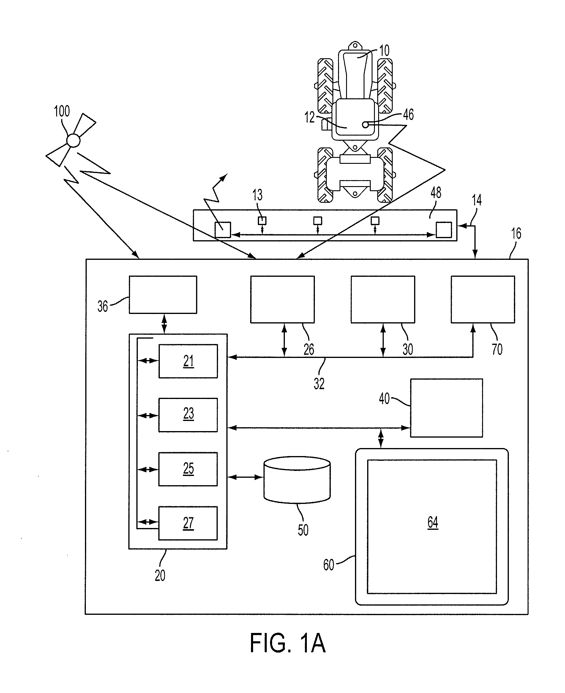
[0049]Referring now to drawings wherein like reference numbers refer to like elements, FIG. 1A, which is a schematic diagram of the control system according to a non-limiting embodiment, shows a control system 16 for controlling an agricultural machine system 10 (e.g., a tractor). It should be understood that non-limiting embodiments of the present application have applicability to any complex or sophisticated type of machine. To illustrate the application of the non-limiting embodiments, however, implementation in an agricultural machine system 10 (hereinafter referred to as tractor 10) operating on a given land territory is shown in the present drawings. The mode of operation of the present control system for the tractor 10 are known to one of ordinary skill. Reference is made to the illustrated hardware elements which in combination with unique aspects of the interactive display capabilities as described herein form the inventive aspects of non-limiting embodiments of the present...


PUM


Abstract

A method and system for controlling a display in a machine operating in a work area. A plurality of views are displayed on a screen, each of the plurality of views corresponding to a plurality of functions. A user of the machine is allowed to simultaneously monitor the work area and control one or more of the plurality of functions by way of one or more of the plurality of views. The functions include one or more physical activities performed by an implement, connected to the machine, in the work area. The user is allowed to control, via the display, the one or more physical activities using software executed on the machine while monitoring the work area.

Description

RELATED APPLICATIONS[0001]This application claims priority from U.S. Provisional Patent Application No. 61 / 790,974, filed on Mar. 15, 2013, in the United States Patent and Trademark Office, the disclosure of which is hereby incorporated herein in its entirety by reference.BACKGROUND[0002]1. Field[0003]One or more non-limiting embodiments relate to a system and method for the simplified and personalized display and control of complex machinery.[0004]2. Description of the Related Art[0005]The control of sophisticated and complex machinery in a simplified system for display is of paramount importance. When an operator of a complex machine, such as a farm tractor needs to control multiple features and function of the device, that operator is often confronted with a technical overload. For example, in farm tractors, there are typically independent critical systems and independent interfaces for the tractor and also for an implement and / or attachment of the tractor performing work functio...

Claims


Application Information

Patent Timeline
Patent Type & Authority Applications(United States)
IPC IPC(8): A01B76/00G06F3/147
CPCA01B76/00G06F3/147H04N7/18A01B69/001A01B69/008G16Z99/00G06F3/00
Inventor MARKOV, DIMITREBOAL, JOHNSTEFANOV, STEFANWALTER, ANDREWSTEPHENS, HEATHSORBE, BRIANGOMES, MICHAEL
Owner TOPCON POSITIONING SYST INC
Why Eureka
Try Eureka