Antenna Device

Active Publication Date: 2016-02-11
SAMSUNG ELECTRONICS CO LTD
View PDF10 Cites 25 Cited by
  • Summary
  • Abstract
  • Description
  • Claims
  • Application Information

AI Technical Summary

Benefits of technology

[0019]In addition, even if antenna devices are mounted close to each other along an edge of an electronic device, a polarization loss can be minimized and a

Problems solved by technology

In a case where such an antenna device is mounted in a miniaturized, thinned, and light-weight electronic device, such as a mobile communication terminal, being under mounting space constraints is unavoidable.
However, since the electronic device does not provide a sufficient length for allowing the mounting of the radiator of the antenna in the thickness direction of the electronic device, it is not easy to implement a polarized wave in the thickness direction (hereinafter, referred to a

Method used


Image

  • Antenna Device
  • Antenna Device
  • Antenna Device

Examples


Example

[0074]Hereinafter, an antenna device 100 according to a first embodiment will be described with reference to FIGS. 3 to 8.

[0075]FIG. 3 is a sectional view schematically illustrating an antenna device 100a according to the first embodiment among various embodiments of the present disclosure. FIG. 4 is a perspective view schematically illustrating the antenna device 100a according to the first embodiment among various embodiments of the present disclosure. FIG. 5 is a view illustrating a vertical polarization radiation pattern generated in a radiation unit 200a in the antenna device 100a according to the first embodiment among various embodiments of the present disclosure.

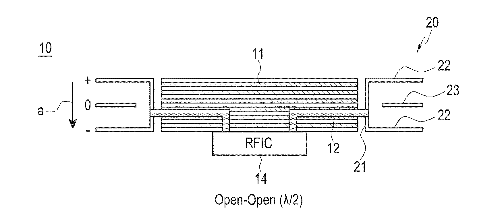
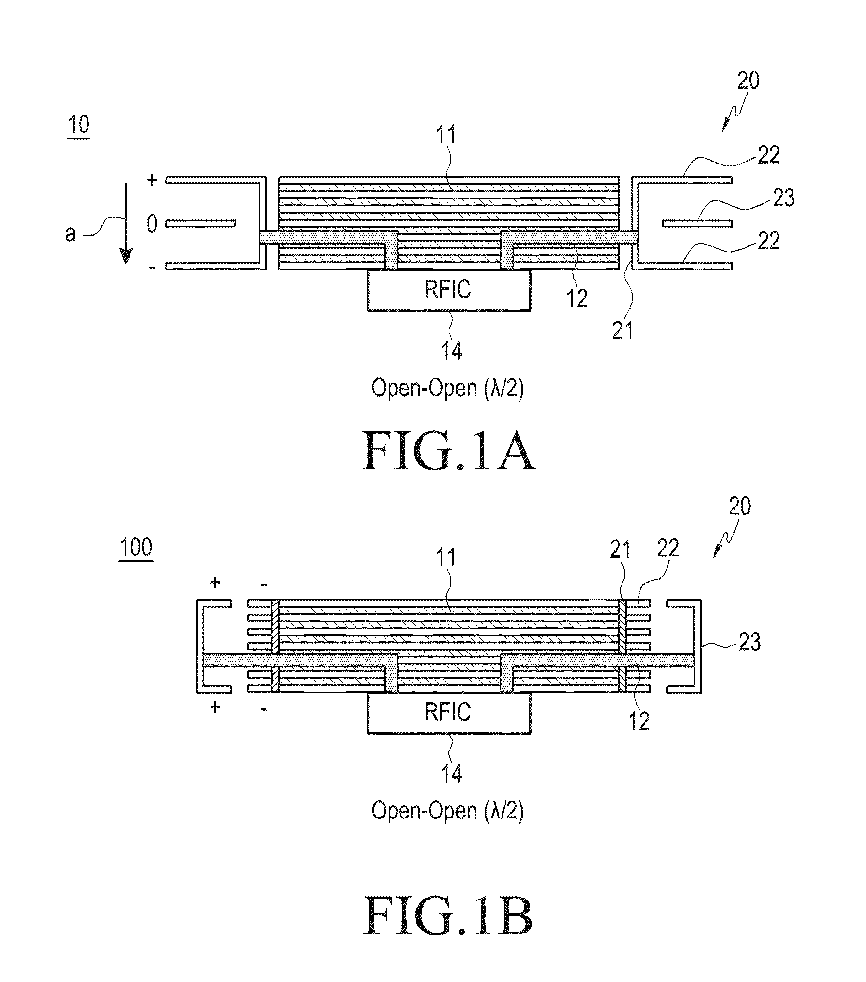
[0076]Referring to FIGS. 3 to 5, the antenna device according to the first embodiment has the same configuration as the antenna device illustrated in FIG. 1A described above, and corresponds to an embodiment of an open stub structure among the antenna devices of the present disclosure.

[0077]As described above, the an...

Example

[0086]Hereinafter, an antenna device 100b according to a second embodiment will be described with reference to FIGS. 9 to 12.

[0087]FIG. 9 is a view schematically illustrating an antenna device 100b according to the second embodiment among various embodiments of the present disclosure. FIG. 10 is a perspective view illustrating a state in which a radiation unit 200b is mounted on a board unit 110b in the antenna device 100b according to the second embodiment among various embodiments of the present disclosure.

[0088]The radiation unit 200b according to the second embodiment of the present disclosure may include a radiator 230b and a ground unit 220b. The radiator 230b and the ground unit 220b are positioned around a peripheral surface of the board unit 110b, and the radiator 230b according to the second embodiment may be provided to face the peripheral surface of the board unit 110b within the width of the board unit 110b.

[0089]The radiator 230b may be spaced apart from the periphera...

Example

[0095]Hereinafter, an antenna device 100c according to a third embodiment will be described with reference to FIGS. 13 to 17.

[0096]FIG. 13 is a view schematically illustrating the antenna device 100c according to the third embodiment among various embodiments of the present disclosure. FIG. 14 is a perspective view illustrating a state in which a radiation unit 200c is mounted on a board unit 110c in the antenna device 100c according to the third embodiment among various embodiments of the present disclosure.

[0097]Referring to FIGS. 13 and 14, a radiation unit 200c according to third embodiment of the present disclosure may implement a radiation pattern in the form of a traveling wave. The radiation unit 200c according to the third embodiment of the present disclosure may include radiation members 220c and guide radiation members 250c.

[0098]The radiation members 220c are positioned on a peripheral surface of the board unit 110c, and may be arranged to face each other with the width...


PUM


Abstract

According to various embodiments, an antenna device may include: a board unit; a power feeding unit provided in the board unit; and radiation units connected to the power feeding unit to be fed with a power feeding signal. The radiation units may be provided to face each other within a width of the board unit along a periphery of the board unit. The device as described above may be implemented more variously according to embodiments.

Description

CROSS-REFERENCE TO RELATED APPLICATION[0001]This application claims the priority under 35 U.S.C. §119(a) to Korean Application Serial No. 10-2014-0100691, which was filed in the Korean Intellectual Property Office on Aug. 5, 2014, the entire content of which is hereby incorporated by reference.TECHNICAL FIELD[0002]Various embodiments of the present disclosure relate to an antenna device.BACKGROUND[0003]Recently, wireless communication techniques have been implemented by various methods, such as Wireless Local Area Network (W-LAN) represented by Wi-Fi technique, Bluetooth, and near field communication (NFC), in addition to commercial mobile communication network connection. Mobile communication services were initiated from a first generation mobile communication service centered on voice communication, and have gradually been developed to a super-high speed and large capacity service (e.g., a high quality video streaming service). It is expected that a next generation mobile communic...

Claims


Application Information

Patent Timeline
IPC IPC(8): H01Q9/04H01Q3/24H01Q21/24
CPCH01Q9/045H01Q21/24H01Q3/24H01Q9/0414H01Q21/28
Inventor KO, SEUNG-TAEKIM, YOON-GEONBAEK, KWANG-HYUNHONG, WON-BIN
Owner SAMSUNG ELECTRONICS CO LTD
Why Eureka
Try Eureka