Process integrating a solid oxide fuel cell and an ion transport reactor

a solid oxide fuel cell and ion transport technology, applied in the direction of cell components, separation processes, electrochemical generators, etc., can solve the problems of loss of efficiency, significant portion of heat energy is rejected, limited efficiency, etc., to reduce the required ion transport membrane area, improve the control of the steam to oxygen ratio, and reduce the power required to compress oxygen

Inactive Publication Date: 2000-01-25
PRAXAIR TECH INC
View PDF15 Cites 50 Cited by
  • Summary
  • Abstract
  • Description
  • Claims
  • Application Information

AI Technical Summary

Benefits of technology

It is yet another object of the invention to place the anode side of the fuel cell in series with anode side of a reactively purged ion transport membrane and add excess fuel to the fuel cell anode feed to be available as reactant in the purge stream and thereby raise the efficiency of the fuel cell energy conversion.
A first portion of the gaseous fuel 30 is delivered to the first anode side 16 of the solid oxide fuel cell 10. A second portion 30' of the gaseous fuel 30 can be delivered directly to the second anode side 50 of the first ion transport reactor 11. Preferably, the combustion products 68 serve as a diluent and are combined at junction 108 with the second portion 30' of the gaseous fuel 30 gas to purge the second anode side 50. Most preferably, all gaseous fuel 30 passes through the first anode side 16 to increase the average fuel partial pressure at the solid oxide fuel cell 10 anode and thereby maximize the efficiency of the fuel cell since a high fuel partial pressure will enhance the reaction kinetics on the fuel cell anode and thereby minimize polarization losses.

Problems solved by technology

Conventional electrical power generation uses a thermal / mechanical process the efficiency of which is limited by the Carnot cycle.
The Carnot cycle mandates that, even under ideal conditions, a heat engine cannot convert all the heat energy supplied to it into mechanical energy, and therefore a significant portion of the heat energy is rejected.
The rejected heat energy causes a loss in efficiency.
Electric power generating systems using solid oxide fuel cells are limited in attainable efficiencies due to several factors including: (1) internal electrical losses primarily in the electrodes, (2) the high temperature in the range of about 700.degree. C. to about 1,000.degree. C. to which air must be heated; and (3) the fact that only a portion of the oxygen contained within the hot air, typically on the order of between 20% to 30% by volume of the oxygen available, is transported through the ceramic membrane for reaction with the gaseous fuel.
Part of the energy added to the retentate and permeate streams is lost as the result of pressure drop and limited effectiveness of optional recuperative heat exchangers.

Method used


Image

  • Process integrating a solid oxide fuel cell and an ion transport reactor
  • Process integrating a solid oxide fuel cell and an ion transport reactor
  • Process integrating a solid oxide fuel cell and an ion transport reactor

Examples


example 2

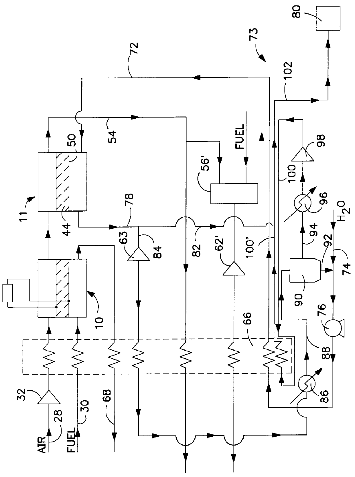
FIG. 7 schematically represents another integrated system in accordance with the invention. This system is particularly effective for the production of essentially oxygen-free nitrogen with the option for the co-production of oxygen and carbon dioxide. Utilizing the parameters presented in Table 3 below, the solid oxide fuel cell 10 is sized to deliver sufficient power to drive the air compressor 162.

An oxygen-containing gas feed 28, preferably air, is compressed by air compressor 162 to a pressure of about 155 psia. The compressed air is then preheated, such as by recuperative heat exchanger 66, to a temperature of about 800.degree. C. and introduced to the first cathode side 14 of the solid oxide fuel cell. Gaseous fuel 30 is introduced to the first anode side 16 and exothermally reacted with oxygen ions transported through the ceramic membrane 12 generating heat, electricity and anode side stream 68 that is a mixture of combustion products and gaseous fuel. The electric power gen...


PUM

PropertyMeasurementUnit
temperatureaaaaaaaaaa
operating temperatureaaaaaaaaaa
temperatureaaaaaaaaaa

Abstract

An integrated system utilizing a solid oxide fuel cell and at least one ion transport reactor to generate electric power and a product gas by delivering an oxygen-containing gas, typically air, to a first cathode side of the solid oxide fuel cell and delivering a gaseous fuel to a first anode side. Oxygen ions are transported through a membrane in the fuel cell to the first anode side and exothermally react with the gaseous fuel to generate electric power and heat. The heat and oxygen transport produces a higher-temperature, reduced-oxygen-content gaseous retentate stream exiting the cathode side of the solid oxide fuel cell which is delivered to a first ion transport reactor where a substantial portion of the residual oxygen is transported through an oxygen selective ion transport membrane. A product gas stream is then recovered.

Description

This invention relates to a process for the co-generation of power and at least one product gas. More particularly, the process integrates a solid oxide fuel cell and an ion transport reactor.Electrical power is traditionally generated by a thermodynamic process. Heat, for example, may be generated by burning oil in a boiler to superheat pressurized water. The superheated water is expanded into pressurized steam that mechanically rotates a turbine. Rotation of the rotor windings of an electric generator rotor connected to the turbine through an appropriate magnetic field generates electrical power.Conventional electrical power generation uses a thermal / mechanical process the efficiency of which is limited by the Carnot cycle. The Carnot cycle mandates that, even under ideal conditions, a heat engine cannot convert all the heat energy supplied to it into mechanical energy, and therefore a significant portion of the heat energy is rejected. In the Carnot cycle, an engine accepts heat ...

Claims


Application Information

Patent Timeline
Patent Type & Authority Patents(United States)
IPC IPC(8): B01D53/32C01B3/00C01B3/36C01B3/38C01B13/02H01M8/12H01M8/06H01M8/04H01M8/02H01M8/10H01M14/00
CPCB01D53/326C01B3/36C01B3/386C01B13/0251H01M8/06H01M8/0662H01M8/1206C01B2210/0046C01B2210/0051C01B2210/0062H01M8/04014H01M8/04022H01M2008/1293H01M2300/0074Y02E60/521Y02E60/525H01M8/1231Y02E60/50Y02P20/129H01M8/00H01M8/24
Inventor PRASAD, RAVIGOTTZMANN, CHRISTIAN FRIEDRICHKESKAR, NITIN RAMESH
Owner PRAXAIR TECH INC
Why Eureka
Try Eureka