Automatic Lubrication System with Detune

a lubrication system and automatic technology, applied in the field of lubrication systems, can solve problems such as significant damage to hammers

Active Publication Date: 2016-02-18
CATERPILLAR INC
View PDF10 Cites 9 Cited by
  • Summary
  • Abstract
  • Description
  • Claims
  • Application Information

AI Technical Summary

Benefits of technology

[0005]The disclosure described, in one aspect, a lubrication system for a tool powered by a drive fluid. The lubrication system includes a lubricant charge chamber having a variable volume, a drive fluid valve member and a detune valve member. The drive fluid valve member is movable from a first position to a second position in response to pressure of drive fluid to reduce the volume of the lubricant charge chamber. The detune valve member is movable operable between a first position and a second position in response to lubricant pressure within the lubricant charge chamber. The detune valve member is adapted to permit a fluid connection between an inlet fluid passage and a bypass fluid passage when the detune valve member is in the first position and to disengage said fluid connection between the inlet fluid passage and the bypass fluid passage when the detune valve member is in its second position.
[0006]The disclosure describes, in anothe

Problems solved by technology

Operating the hammers without lubrication ca

Method used


Image

  • Automatic Lubrication System with Detune
  • Automatic Lubrication System with Detune
  • Automatic Lubrication System with Detune

Examples


Embodiment Construction

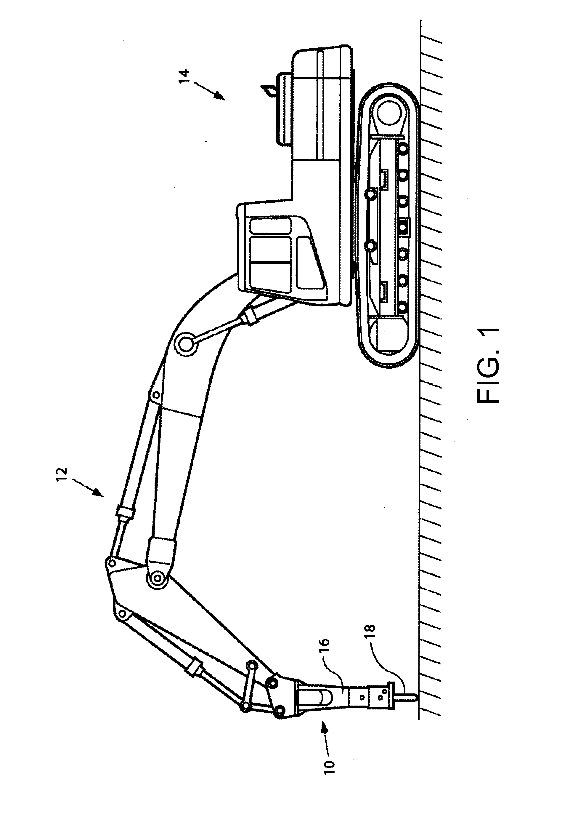
[0011]Referring to FIG. 1, a work tool 10 powered by a drive fluid is attached to a boom 12 of an excavator 14. The work tool 10, however, may be connected to any suitable machine or base. In the depicted embodiment, the work tool 10 is a hydraulic or pneumatic powered breaking tool, such as a demolition hammer. When attached to the excavator 14, as illustrated, the excavator's hydraulic system may be used to power the tool. Thus, the drive fluid may be hydraulic fluid. The present disclosure, however, is applicable to other hydraulic or pneumatic tools and to tools powered by other means. The work tool 10 includes a power cell 16 and a tool 18. The power cell 16 is configured to provide a breaking force via the tool 18 to an object, such as rocks, concrete, asphalt, frozen ground, or other hard objects.

[0012]While the arrangement is illustrated in connection with an excavator 14, the arrangement disclosed herein has universal applicability in various other types of machines as well...


PUM


Abstract

Lubrication system includes a drive fluid valve member and a detune valve member. The drive fluid valve member is movable from a first to a second position in response to drive fluid pressure to reduce the volume of a variable volume lubricant charge chamber. The detune valve member is movable from a first to a second position in response to lubricant pressure within the lubricant charge chamber, and is adapted to permit fluid communication between inlet and bypass fluid passages in its the first position and to disengage the fluid connection in its second position.

Description

TECHNICAL FIELD[0001]This patent disclosure relates generally to a lubrication system for and method of lubricating a work tool powered by a drive fluid, and more particularly to a lubrication system for a hydraulic or pneumatic hammer.BACKGROUND[0002]Demolition hammers are used on work sites to break up objects such as rocks, concrete, asphalt, frozen ground, or other hard objects. The hammers may be mounted to machines, such as backhoes and excavators, or may be hand-held. The hammers may be powered by a hydraulic or pneumatic pressure source. In operation, a high pressure fluid drives a piston to strike a tool bit, which in turn, strikes rock, concrete, asphalt or other hard object to be broken up.[0003]Lubrication systems are used to supply lubricant, such as grease, to bearing surfaces in the hammer to reduce friction between moving parts, such as between the tool bit and bushings that are used to align the tool bit. The lubrication system may be separate from the hammer, for e...

Claims


Application Information

Patent Timeline
IPC IPC(8): B25D17/26E02F9/22
CPCE02F9/2267B25D17/26B25D9/08B25D9/12B25D9/18B25D9/20B25D2209/007B25D2250/371F16N7/36F16N29/04F16N2260/04
Inventor MOORE, CODY
Owner CATERPILLAR INC
Why Eureka
Try Eureka