On-board device, signaling system and control method of moving vehicle

a technology of signaling system and moving vehicle, which is applied in the direction of electric devices, process and machine control, instruments, etc., can solve the problems of limiting the cost reduction, affecting the safety of the vehicle, so as to reduce the space of the device and so on, reduce the introduction cost, and facilitate the treatment of the device

Inactive Publication Date: 2016-02-18
MITSUBISHI HEAVY IND LTD
View PDF5 Cites 15 Cited by
  • Summary
  • Abstract
  • Description
  • Claims
  • Application Information

AI Technical Summary

Benefits of technology

[0019]Therefore, an object of the present invention is to provide a signaling system in which a space for devices and so on can be reduced. Also, another object of the present invention is to provide a signaling system in which an introduction cost can be reduced. Still another object of the present invention is to provide a signaling system in which the treatment of devices is easy.
[0032]According to the present invention, the space of the devices and so on can be reduced. Also, according to the present invention, the reduction of the introduction cost becomes possible. Moreover, according to the present invention, the treatment of the devices becomes easy.

Problems solved by technology

Therefore, considering the system configuration while paying attention to the safety of the signaling system, it is not possible to step out from the above configuration and there is a limit in the cost reduction.
Therefore, each device is allocated with a very large load.
For this reason, each device is extremely large in size and is expensive.

Method used


Image

  • On-board device, signaling system and control method of moving vehicle
  • On-board device, signaling system and control method of moving vehicle
  • On-board device, signaling system and control method of moving vehicle

Examples


first embodiment

1. Configuration

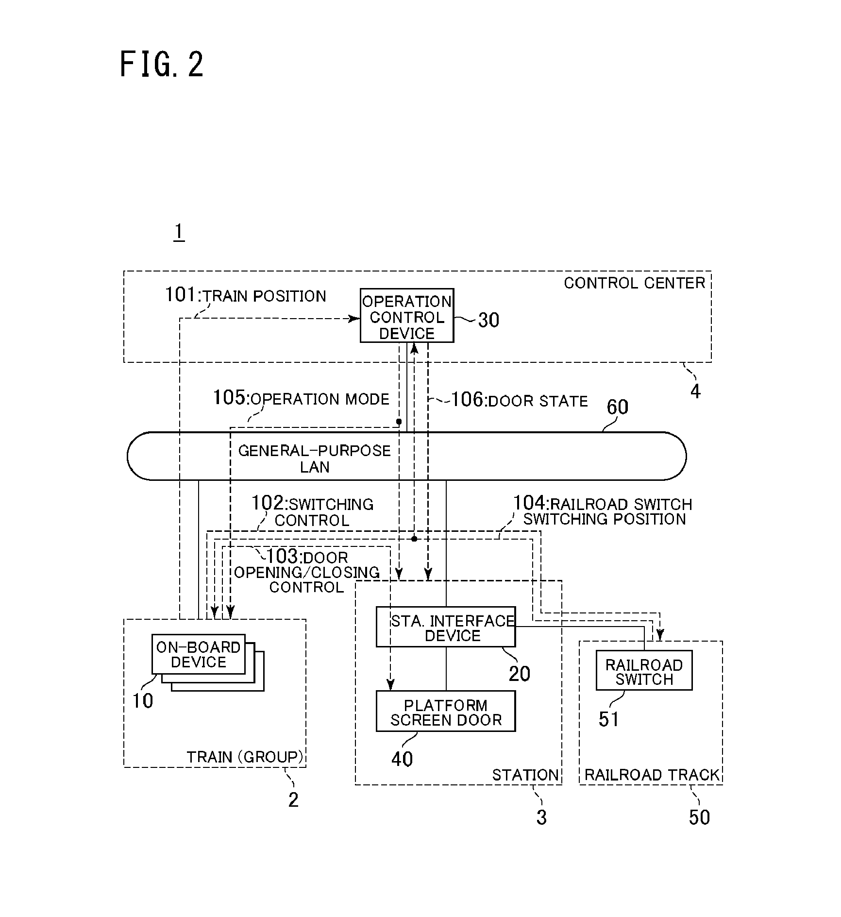
[0055]The configuration of a signaling system according to a first embodiment of the present invention will be described. FIG. 2 is a block diagram showing the configuration of the signaling system according to the present embodiment. The signaling system 1 is divided into sections of a control center 4, (a group of) trains 2, stations 3 and railroad tracks 50.

[0056]The control center 4 grasps an operation state of the trains 2 in the whole of railroad divisions. The control center 4 is provided with an operation control device 30. The operation control device 30 is connected with (on-board devices 10 of) the trains 2 and (station interface devices 20 of) the stations 3 through a general-purpose LAN 60 to be communicable bi-directionally. The operation control device 30 receives data of the trains 2 (e.g. train positions 101) from the trains 2, receives data of platform screen doors, train doors and railroad switches (e.g. door states 106, and railroad switch switchi...

second embodiment

[0121]The signaling system according to a second embodiment of the present invention will be described. In the present embodiment, the train interval protection in case of inter-station traveling of the train 2 in an operation with a failure (a failure mode) in the signaling system having the configuration described in the first embodiment will be described. Below, different points from the first embodiment will be mainly described.

1. Configuration

[0122]The control device of the on-board device 10 will be described.

[0123]FIG. 10 is a block diagram showing a configuration example of the traveling route securement determining section 70 of the control device of the signaling system according to the present embodiment. The traveling route securement determining section 70 is further provided with a route determining section 75 and a standby position traveling section 76 in addition to the configuration of FIG. 4A. The route determining section 75 determines a route to avoid a failure p...

third embodiment

[0152]The signaling system to according a third embodiment of the present invention will be described. In the present embodiment, in the signaling system which has the configuration described in the second embodiment, the train interval protection will be described in case of inter-station traveling of the train 2 in the end station section in the normal mode. Below, the difference points from the second embodiment will be mainly described.

1. Configuration

[0153]The configuration of the present embodiment is the same as that of the signaling system according to the second embodiment.

2. Operation

[0154]Next, the operation of the signaling system according to the present embodiment will be described. In this case, as the operation of the signaling system, the train interval protection will be described in case of inter-station traveling of the train 2 in the end station section in the normal mode.

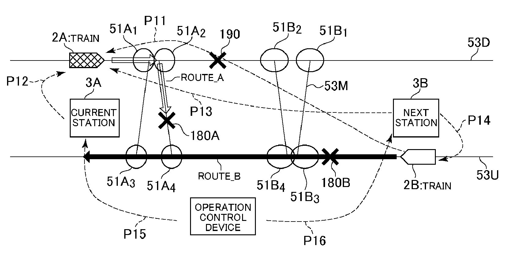
[0155]The state of the railroad line to which the signaling system is applied will be descr...


PUM


Abstract

An on-board device is loaded in a moving vehicle traveling on a track. The on-board device acquires failure data indicating a failure on the track. Based on the failure data, a traveling route is determined in case of the failure. The securement of the traveling route is determined based on station related data that is acquired from a station interface device of a station to which a branch on the route belongs and which indicates data of the branch, and different moving vehicle related data that is acquired from a different moving vehicle competing in at least a part of the traveling route and that indicates data of the different moving vehicle. The traveling of the moving vehicle is determined regarding the secured traveling route based on the different moving vehicle related data.

Description

RELATED APPLICATIONS[0001]The present application is a National Phase of International Application Number PCT / JP2013 / 059741, filed Mar. 29, 2013.TECHNICAL FIELD[0002]The present invention relates to an on-board device, a signaling system and a method of controlling a moving vehicle, and especially, to an on-board device of a moving vehicle moving on a track, a signaling system and a method of controlling the moving vehicle.BACKGROUND ART[0003]A moving vehicle (a train) traveling on a track as in a new transportation system and a railway is known. A signaling system which controls the traveling of such a moving vehicle is known. The conventional signaling system is of a central supervisory control-type. In the central supervisory control-type signaling system, devices for a main safety function (a protection function) are concentrates in a control center and the traveling states of trains in a whole railroad division are grasped and managed, in order to realize a function safety. The...

Claims


Application Information

Patent Timeline
Patent Type & Authority Applications(United States)
IPC IPC(8): B61L27/00B61L23/04B61L23/14
CPCB61L27/0005B61L23/04B61L2205/00B61L27/0077B61L2201/00B61L23/14B60L15/40B61L15/0072B60L3/0015B60L3/0023B60L3/102B60L3/106B60L3/12B60L2200/26B60L2240/12B60L2240/461B60L2240/465B60L2240/62B60L2240/70B60L2250/16Y02T90/16B61L3/008B61L7/088B61L19/06B61L23/20B61L2019/065Y02T10/72B61L27/40B61L27/70B61L27/20
Inventor MIYAJIMA, YUTAKA
Owner MITSUBISHI HEAVY IND LTD
Why Eureka
Try Eureka