
Cooling Ring

a cooling ring and guiding technology, applied in the direction of electrical apparatus, dynamo-electric machines, hoisting equipment, etc., can solve the problems of increasing the cost of bearings, limiting the inside diameter through which cooling air can flow, and limiting the efficiency of existing measures, so as to reduce the loss of air flow and improve efficiency

Inactive Publication Date: 2016-02-18
SIEMAG TECBERG
View PDF13 Cites 0 Cited by
  • Summary
  • Abstract
  • Description
  • Claims
  • Application Information

AI Technical Summary

Benefits of technology

The invention relates to a cooling system for a rope carrier. The system has two air ducts that run within each other, like rings. These rings can have different diameters and can be sealed to improve efficiency. The system also includes a rotating ring that creates an additional volume for compensating pressure variations. The technical effects of this invention are to reduce air flow loss and provide better cooling performance for rope carriers.

Problems solved by technology

With performance of hoisting machines increasing all the time, the so far existing measures reach their limits economically and technically.
Thus, in the case of a hollow axle, the inside diameter through which cooling air can flow is limited by excessive production costs among other things.
This increase of the bearing diameter disadvantageously results in a cost increase of the bearings, and, in the case of a failure, to a prolonged reacquisition time of a replacement bearing.
Further, when the performance of the hoisting machine increases and the flow cross-section of the hitherto existing solutions is limited, it can become necessary to additionally cool and / or climatize the fed cooling air, which causes further costs with regard to assembly and operation, and greater space requirements of the installation.

Method used


Image

  • Cooling Ring
  • Cooling Ring
  • Cooling Ring

Examples


Embodiment Construction

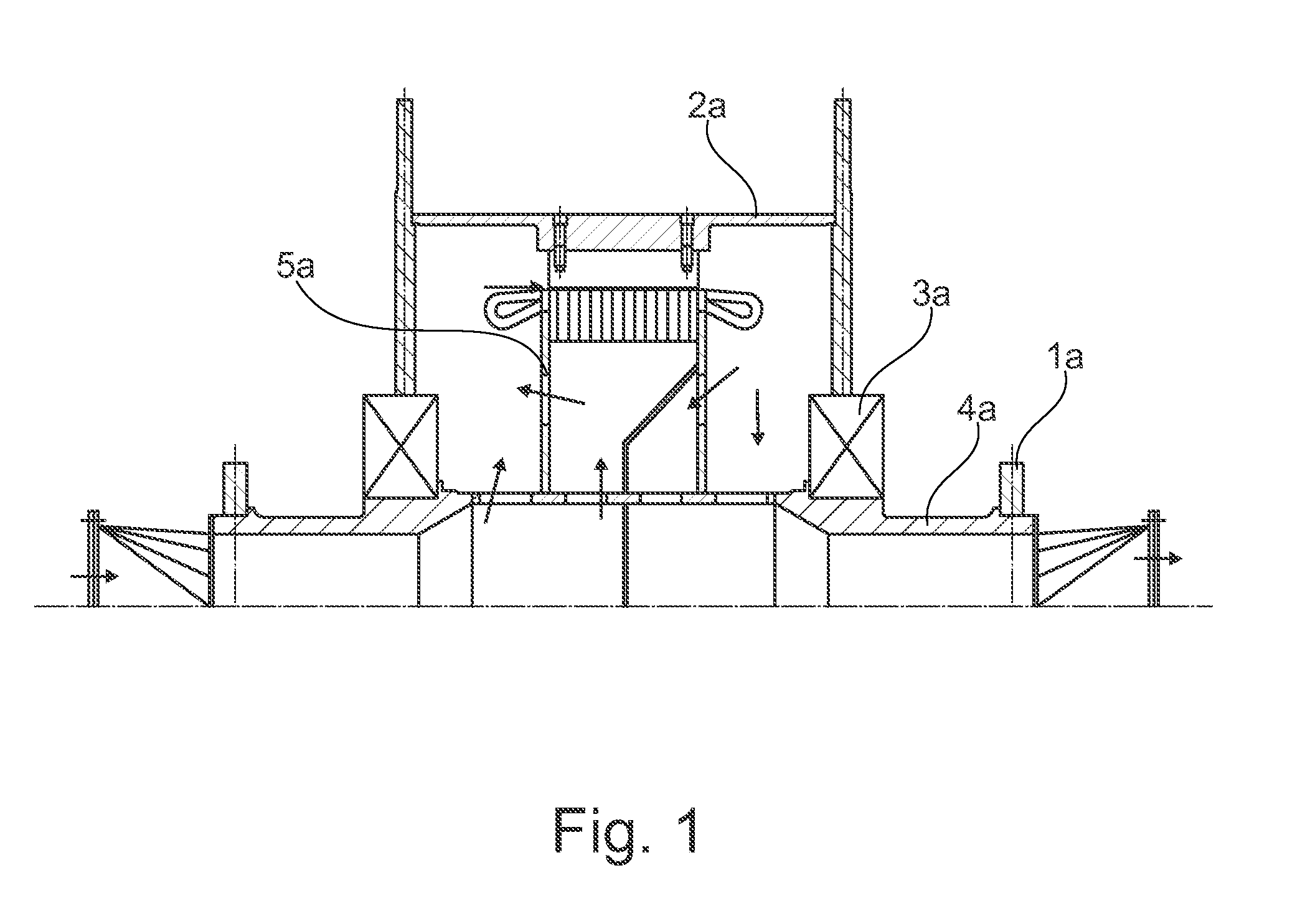
[0020]FIG. 1 shows a known hoisting machine, in which a rope carrier 2a is vented via a hollow main axle 4a. The rope carrier 3a is mounted on the hollow main axle 4a by means of bearings 3a arranged in mirror-image fashion, wherein the hollow main axle 4a is held by bearing supports 1a likewise arranged in mutual mirror-image fashion. In FIG. 1 the arrows indicate the air flow through the arrangement. This flow is fed to the hollow main axle 4a from the right side, then enters the rope carrier 2a through openings, flows through the electrical device 5a within the rope carrier 2a, reenters the hollow main axle 4a through openings and exits the arrangement on the left side. The complicated configuration of the hollow main axle 4a and the associated high manufacturing costs for the axle and the bearings 3a are disadvantageous in this solution.

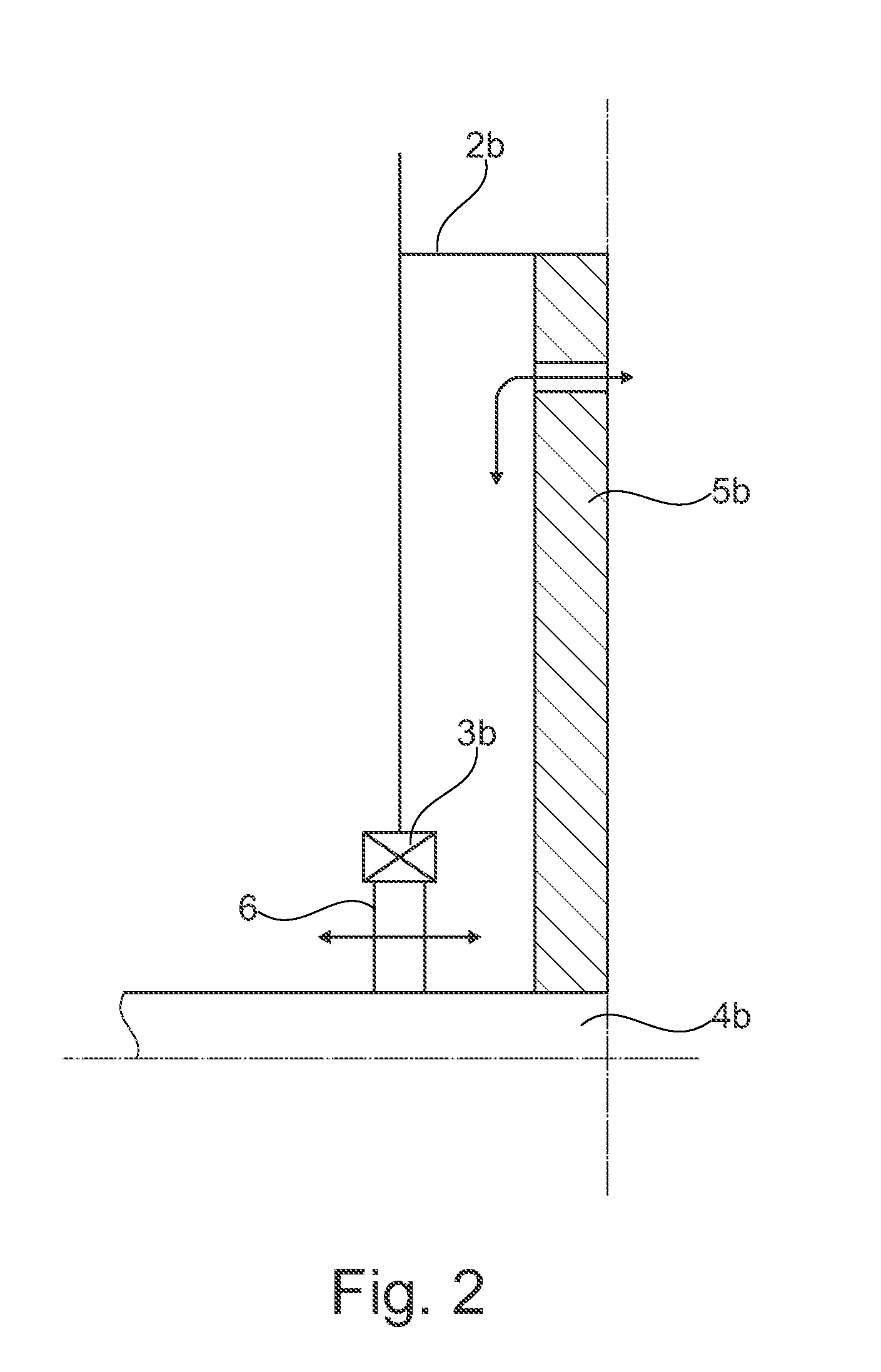
[0021]FIG. 2 shows a further known hoisting machine, wherein the cooling air (arrows) flows into a rope carrier 2 of a hoisting machine via a fl...


PUM


Abstract

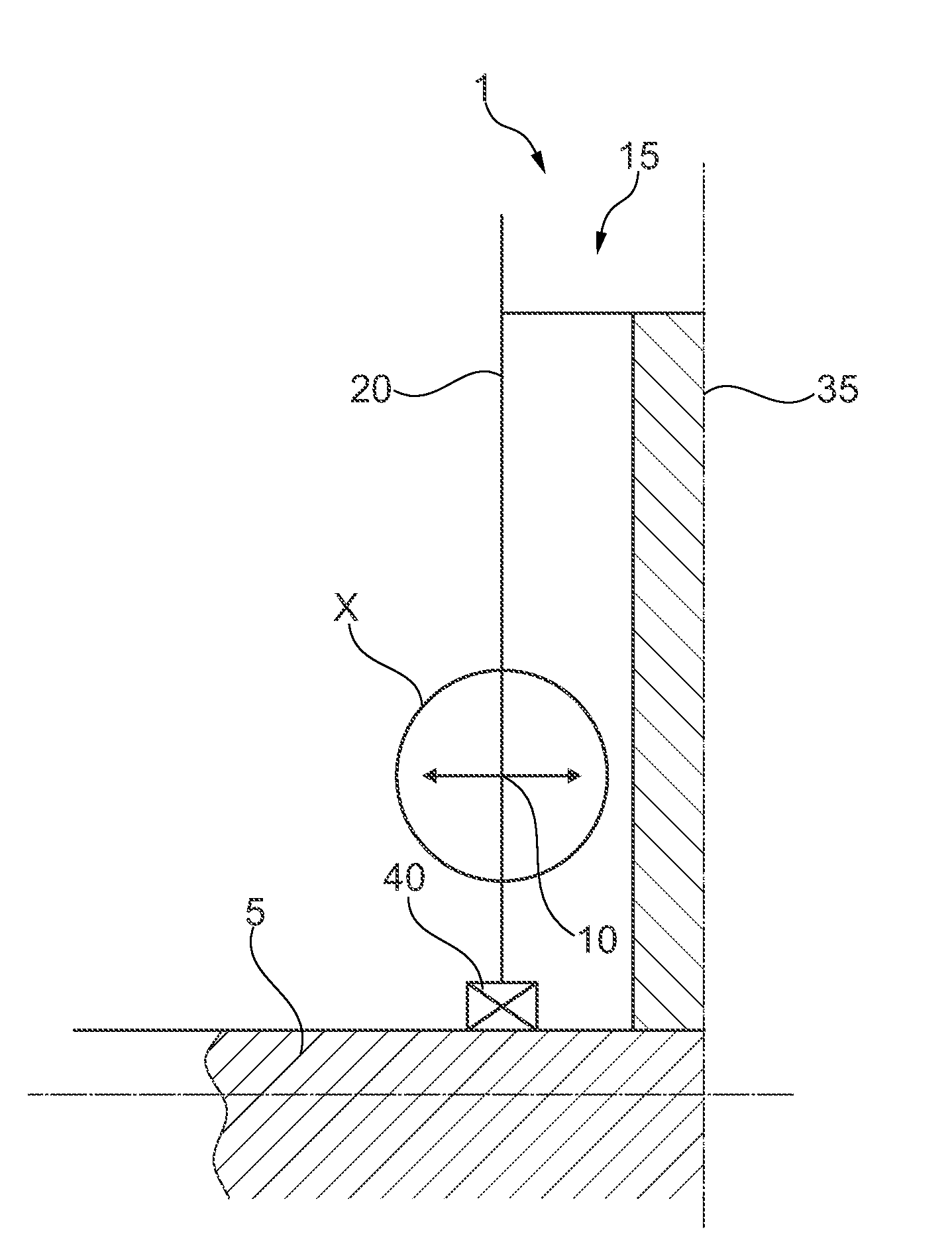
The invention relates to ventilation openings (10) integrated in at least one side plate (20) of the cable carrier (15) of a hauling machine (1). An electrical apparatus (35) is arranged in the interior of the cable carrier (15). A first air guide (30) covers the ventilation openings (10) in the side plate (20). The first air guide (30) is arranged for interactive air exchange with a second air guide (25), wherein the first air guide (30) is movable relative to the second air guide (20).

Description

BACKGROUND OF THE INVENTION[0001]1. Field Of The Invention[0002]The present invention relates to an apparatus for guiding cooling air into a hoisting machine.[0003]2. Brief Description Of The Related Art[0004]Due to the ever greater required performance of hoisting machines, growing demands are made with respect to cooling the electrical devices located in the rope carriers, such as drives or generators. Solutions have already been suggested, such as a hollow axle for feeding cooling air, on which axle the rope carrier is mounted, as well as guiding in and out of cooling air via the sides of the rope carriers by air hoods or stationary flow rings on the axle of the hoisting machine.[0005]With performance of hoisting machines increasing all the time, the so far existing measures reach their limits economically and technically. Thus, in the case of a hollow axle, the inside diameter through which cooling air can flow is limited by excessive production costs among other things. In the ...

Claims


Application Information

Patent Timeline
Patent Type & Authority Applications(United States)
IPC IPC(8): B66D1/28B66D1/12H02K9/04
CPCB66D1/28H02K9/04B66D1/12H02K7/14H02K5/207
Inventor BERNS, JAKOBSONNEBORN, STEPHAN
Owner SIEMAG TECBERG
Learn More