Ladar Point Cloud Compression

a technology of ladar point cloud and compression, applied in distance measurement, surveying and navigation, instruments, etc., can solve the problems of large size, large weight, and large power requirements, and the conventional ladar solution for computer vision problems suffers from high cost, large data bandwidth use, and large data bandwidth us

Active Publication Date: 2016-02-18
AEYE INC
View PDF1 Cites 175 Cited by
  • Summary
  • Abstract
  • Description
  • Claims
  • Application Information

AI Technical Summary

Problems solved by technology

However, conventional ladar solutions for computer vision problems suffer from high cost, large size, large weight, and large power requirements as well as large data bandwidth use.
These complicating factors have largely limited their effective use to costly applications that require only short ranges of vision, narrow fields-of-view and/or slow revisit rates.
However, these conventional systems are believed to suffer from a number of shortcomings.
For example, flash ladar systems require a very high energy per pulse laser, which is not only costly but can also be an eye hazard.
Furthermore, the read-out integrated circuits for flash ladar systems are typically quite noisy, optically and electronically.
Also, the wide field-of-view signal-to-noise ratio

Method used


Image

  • Ladar Point Cloud Compression
  • Ladar Point Cloud Compression
  • Ladar Point Cloud Compression

Examples


Embodiment Construction

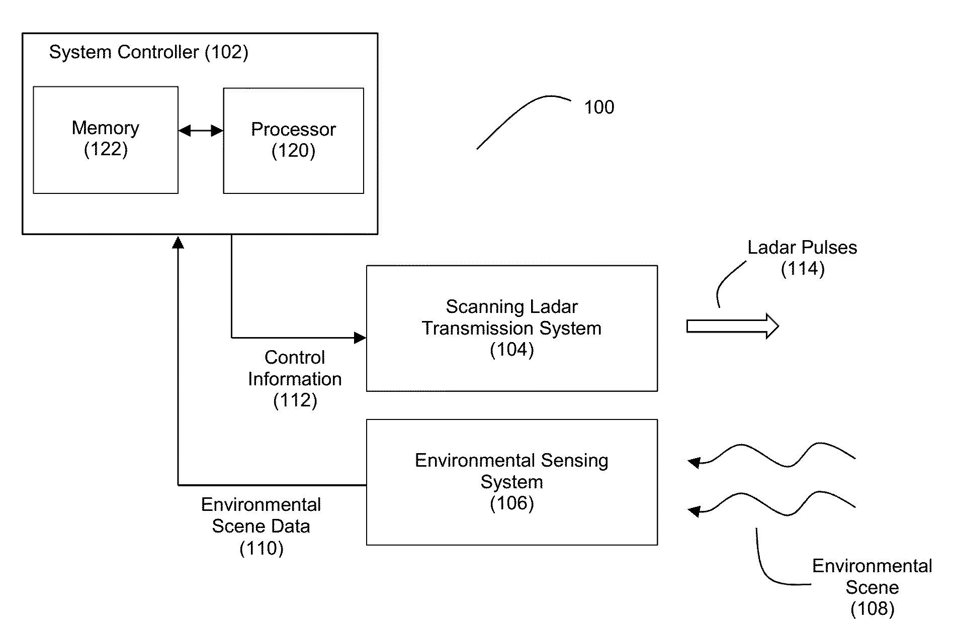
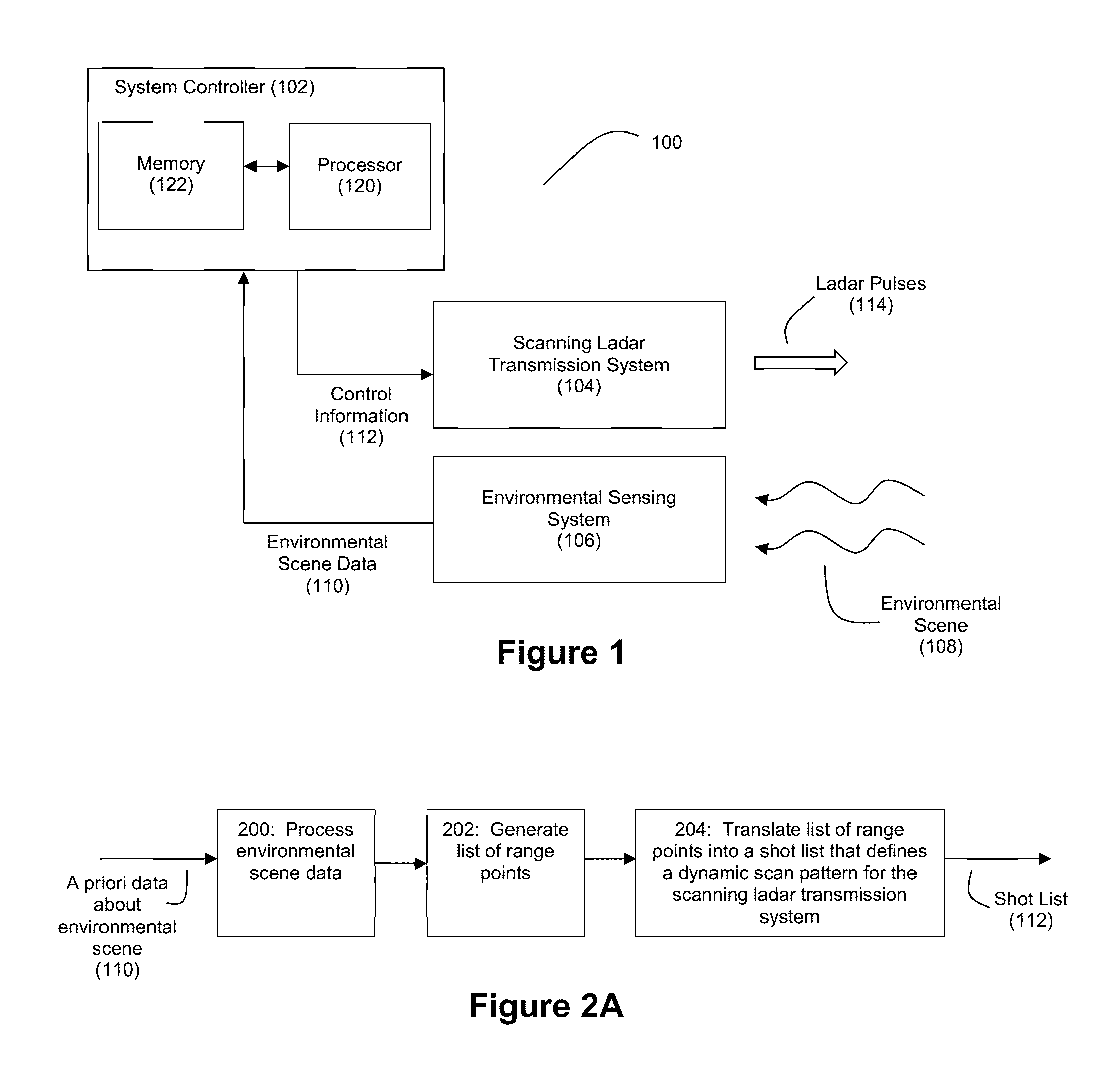
[0035]FIG. 1 illustrates a system 100 for dynamic scanning ladar transmission in accordance with an example embodiment. The system 100 includes a system controller 102 in communication with a scanning ladar transmission system 104 and an environmental sensing system 106. The environmental sensing system 106 can be configured to sense an environmental scene 108 and provide environmental scene data 110 to the system controller 102. Based on an analysis of the environmental scene data 110, the system controller 102 can generate control information 112 for delivery to the scanning ladar transmission system 104. The scanning ladar transmission system, in turn, can transmit ladar pulses 114 in accordance with the control information 112 received from the system controller 102. As explained in further detail below, the scanning ladar transmission system 104 can employ closed loop feedback control of the scan positions for the scanning ladar transmission system 104.

[0036]Although not shown,...


PUM


Abstract

Various embodiments are disclosed ladar point cloud compression. For example, a processor can be used to analyze data representative of an environmental scene to intelligently select a subset of range points within a frame to target with ladar pulses via a scanning ladar transmission system. In another example embodiment, a processor can perform ladar point cloud compression by (1) processing data representative of an environmental scene, and (2) based on the processing, selecting a plurality of the range points in the point cloud for retention in a compressed point cloud, the compressed point cloud comprising fewer range points than the generated point cloud.

Description

CROSS-REFERENCE AND PRIORITY CLAIM TO RELATED PATENT APPLICATIONS[0001]This patent application claims priority to U.S. provisional patent application Ser. No. 62 / 038,065, filed Aug. 15, 2014, the entire disclosure of which is incorporated herein by reference.[0002]This patent application is related to the following patent applications: (1) U.S. patent application Ser. No. ______, entitled “Method and System for Ladar Transmission with Closed Loop Feedback Control of Dynamic Scan Patterns”, filed this same day and identified by Thompson Coburn Attorney Docket Number 56976-147513, (2) U.S. patent application Ser. No. ______, entitled “Method and System for Ladar Transmission with Spinning Polygon Mirror for Dynamic Scan Patterns”, filed this same day and identified by Thompson Coburn Attorney Docket Number 56976-147514, (3) U.S. patent application Ser. No. ______, entitled “Method and System for Ladar Transmission with Interline Skipping for Dynamic Scan Patterns”, filed this same day...

Claims


Application Information

Patent Timeline
IPC IPC(8): G01S7/484G01S7/4861G01S17/10G01S17/86G01S17/87G01S17/89G01S17/931
CPCG01S7/4861G01S7/484G01S17/87G01S17/89G01S17/42G01S7/4814G01S17/10G01S7/4817G01S7/499G01S17/86G01S17/931
Inventor DUSSAN, LUIS, CARLOS
Owner AEYE INC
Why Eureka
Try Eureka