Upsampling and signal enhancement

a signal enhancement and signal technology, applied in image enhancement, image analysis, instruments, etc., can solve the problems of linear models not being able to capture the fast evolving statistics around edges, the band-limitedness does not hold for most images, and the resulting hr image is blued. , to achieve the effect of reducing quality

Active Publication Date: 2016-02-18
FRAUNHOFER GESELLSCHAFT ZUR FOERDERUNG DER ANGEWANDTEN FORSCHUNG EV
View PDF3 Cites 3 Cited by
  • Summary
  • Abstract
  • Description
  • Claims
  • Application Information

AI Technical Summary

Benefits of technology

[0014]The present application exploits the inventors' finding that a signal which is to be quality-improved often suffers from the quality degradation at high frequencies more than compared to low frequencies, and that accordingly a quality improvement is performed most efficiently by combining the signal to be quality improved with a high frequency portion extracted from a sparse approximation for the signal to be quality improved. In accordance with one aspect of the present application, for example, the finding is exploited for upsampling a first signal wherein an initial upsampling process is applied onto the first signal so as to obtain a second signal having a resolution higher than the first signal's resolution. Here, the upsampling process tends to show lower quality for higher frequencies than compared to lower frequencies. In accordance with another aspect of the present application, the above outlined idea as used for signal enhancement may have been quality-degraded by way of, for example, lossy coding. In fact, the concept of signal enhancement of the present application may be seen as part of the upsampling concept of the present application, with the signal enhancement being applied onto the upsample result.

Problems solved by technology

These techniques may cause several artifacts, most commonly, blurring of the resulting HR image.
The assumption of band-limitedness does not hold for most images, due to the existence of sharp edges.
However, these linear models cannot capture the fast evolving statistics around edges.
Increasing the degree of basis functions in these linear models help to capture higher order statistics but result in longer effective support in the spatial domain and hence produce artifacts like ringing around edges.
However, the resulting images still show some artifacts.
However, the downsampling filter may not be known in many cases, or the input image may be camera captured, where the optical anti-alias filter used within the sampling system is not known during the subsequent image processing stages.
Here, the upsampling process tends to show lower quality for higher frequencies than compared to lower frequencies.

Method used


Image

  • Upsampling and signal enhancement
  • Upsampling and signal enhancement
  • Upsampling and signal enhancement

Examples


Embodiment Construction

[0023]Before the description of certain embodiments of the present application, some thoughts shall be outlined which led to the subsequently described embodiments.

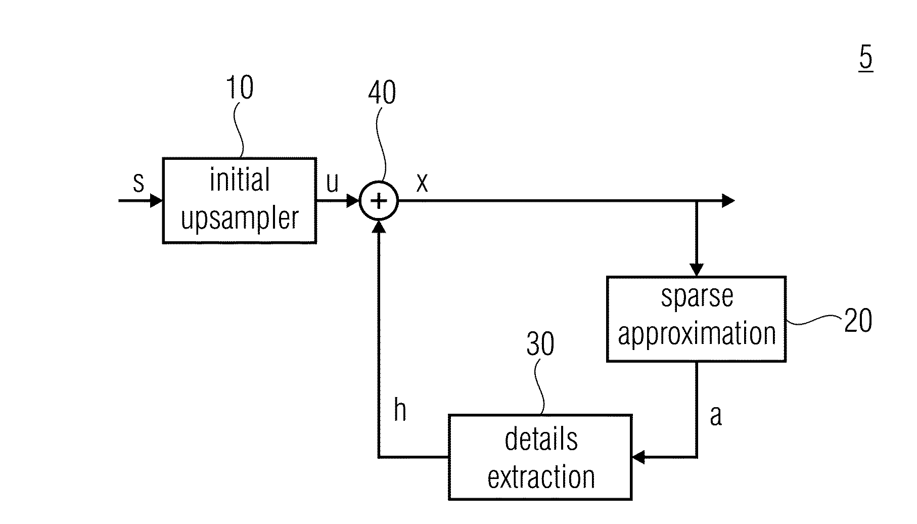
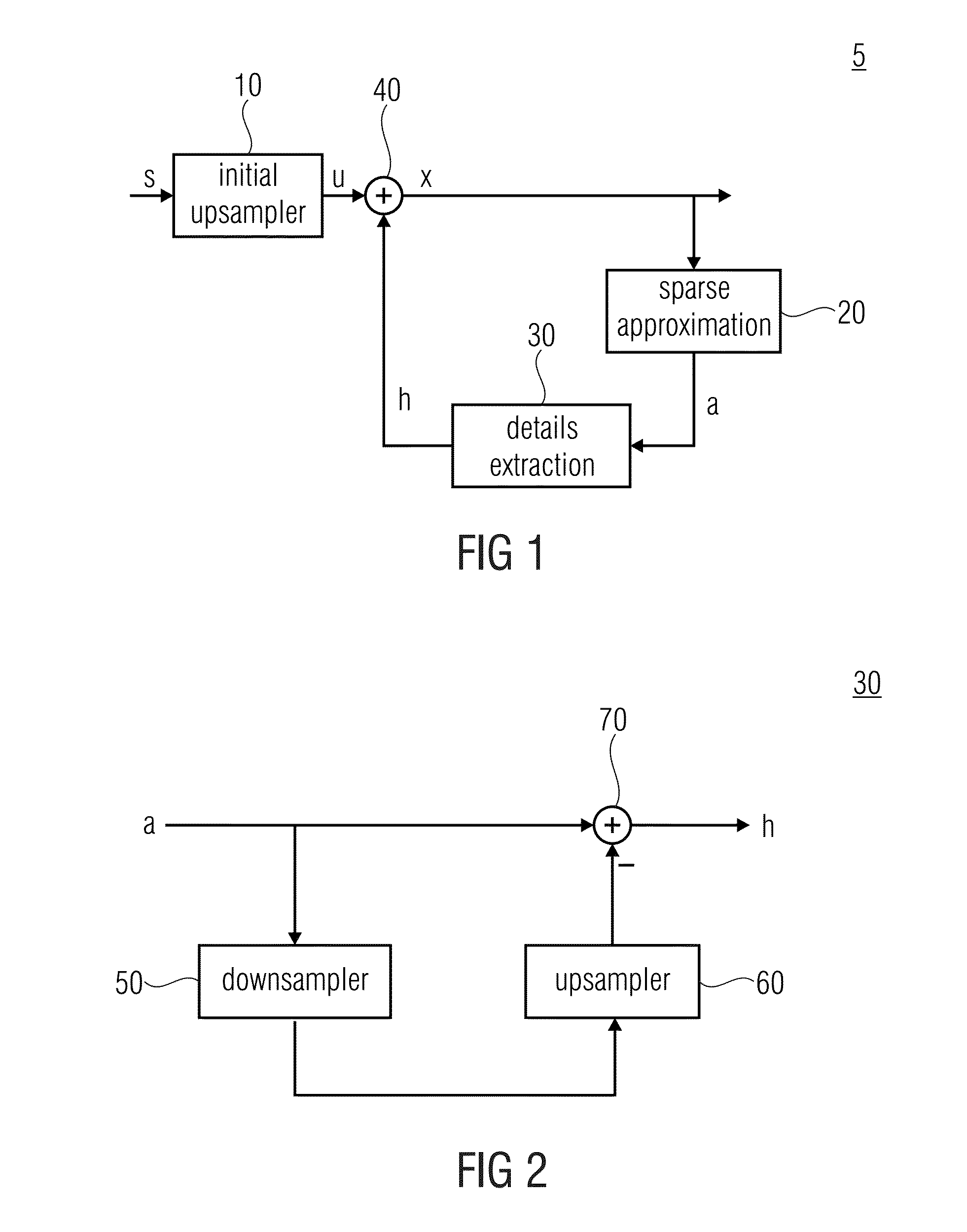
[0024]First of all, it is noted that linear models like FIR filter based interpolation are faithful in interpolating the low frequency components, but distort the high frequency components in the upsampled image. Accordingly, in the embodiments outlined below, the output of such an initial interpolator is combined with detail components from a sparse approximation. For example, this may be realized by way of an iterative framework that performs the combination. The motivation to use the detailed components from a sparse approximation for signal enhancement is motivated by the fact that natural images can be sparsely represented in some domains [Olshausen1996]. The stage of sparse approximation can be viewed as approximating a signal with only a few transform coefficients, e.g. by transforming the signal to a specific doma...


PUM


Abstract

A signal which is to be quality-improved often suffers from the quality degradation in the spatial high frequency region more than compared to the spatial low frequency region. Accordingly a quality improvement is performed efficiently by combining the signal to be quality improved with a high frequency portion extracted from a sparse approximation of the signal to be quality improved.

Description

CROSS-REFERENCE TO RELATED APPLICATIONS[0001]This application is a continuation of copending International Application No. PCT / EP2014 / 058267, filed Apr. 23, 2014, which is incorporated herein by reference in its entirety, and additionally claims priority from European Application No. 13165601.9, filed Apr. 26, 2013, which is also incorporated herein by reference in its entirety.BACKGROUND OF THE INVENTION[0002]The present application is concerned with upsampling and signal enhancement such as in the field of image / video coding.[0003]Image upsampling refers to generating a High Resolution (HR) image from an input Low Resolution (LR) image. This task has regained attention because images / videos are being viewed on displays of varying sizes, like mobile phones, tablets, laptops, PCs, etc. For example, the content for a 1920×1080 display may be available only in a 1280×720 format and needs to be upsampled. More recently, 4K displays are becoming popular and content with a lower resoluti...

Claims


Application Information

Patent Timeline
Patent Type & Authority Applications(United States)
IPC IPC(8): G06T3/40
CPCG06T2207/20024G06T3/4053G06T3/4076
Inventor LAKSHMAN, HARICHARANSCHWARZ, HEIKOMARPE, DETLEVWIEGAND, THOMASKUTYNIOK, GITTAWANG-Q, LIM
Owner FRAUNHOFER GESELLSCHAFT ZUR FOERDERUNG DER ANGEWANDTEN FORSCHUNG EV
Why Eureka
Try Eureka