Differential magnetic tunnel junction pair including a sense layer with a high coercivity portion

a magnetic tunnel junction and sense layer technology, applied in the field of memory devices, can solve the problems that read operations at tas-mram devices may consume more power than read operations at stt-mram devices, and achieve the effects of high coercivity, improved operation of mtj devices, and high coercivity

Inactive Publication Date: 2016-02-18
QUALCOMM INC
View PDF5 Cites 13 Cited by
  • Summary
  • Abstract
  • Description
  • Claims
  • Application Information

AI Technical Summary

Benefits of technology

[0006]A device may include a differential magnetic tunnel junction (MTJ) pair having a first MTJ and a second MTJ that store a value. To read the value, magnetoresistances of the MTJs may be sensed and compared. Mapping a single bit value to the MTJs may enable a high coercivity material (or a magnetically “hard” material) to be included in sense layers of the MTJ devices (because states of the sense layers need not be “toggled” during read operations as in certain conventional self-referenced MTJs). Including the high coercivity material in sense layers may improve operation of an MTJ device, such as by enhancing reliability of the MTJ device by increasing stability of a sense layer. Further, read operation latency may be reduced by avoiding “toggling” of a sense layer during a read operation as in certain conventional self-referenced MTJ devices. In an illustrative implementation, the differential MTJ pair is implemented within a thermal-assisted switching (TAS) spin-torque transfer (STT) magnetoresistive random access memory (TAS-STT-MRAM) device that utilizes both STT and TAS effects to store information at the differential MTJ pair.

Problems solved by technology

Read operations at a TAS-MRAM device may consume more power than read operations at an STT-MRAM device.
The fixed magnetic state may enable STT operation at the differential MTJ pair (because spin-torque may depend on the relative direction of the magnetic states and may be incompatible with conventional self-referenced TAS-MRAM designs).

Method used


Image

  • Differential magnetic tunnel junction pair including a sense layer with a high coercivity portion
  • Differential magnetic tunnel junction pair including a sense layer with a high coercivity portion
  • Differential magnetic tunnel junction pair including a sense layer with a high coercivity portion

Examples


Embodiment Construction

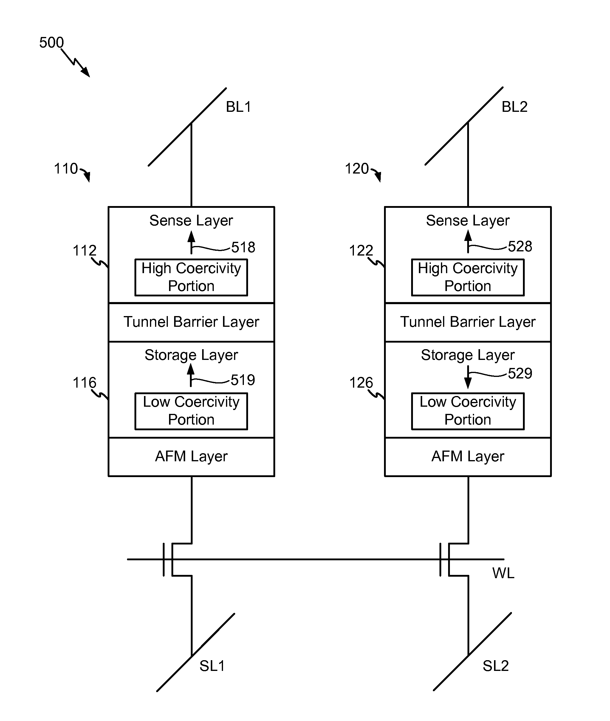
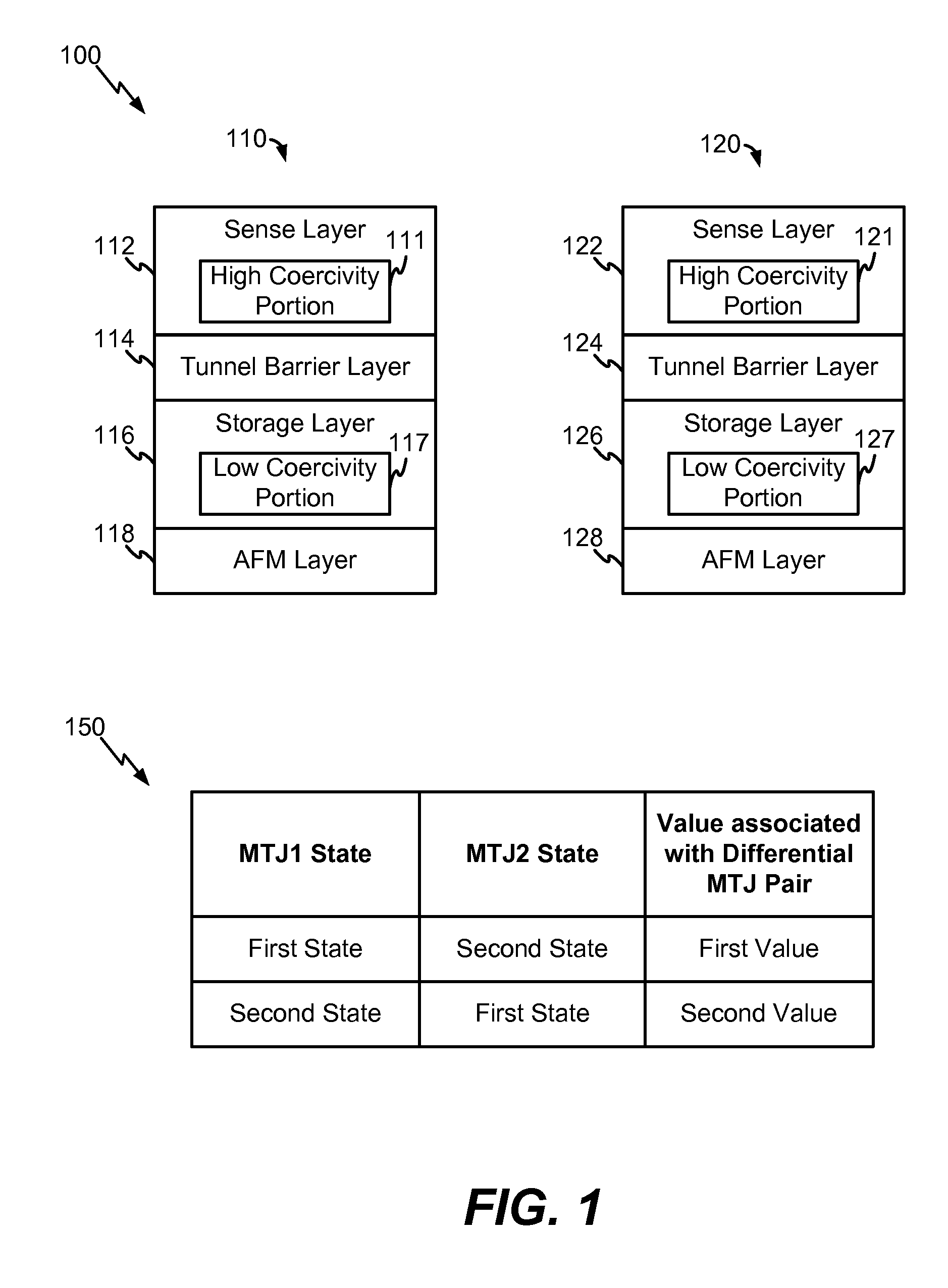
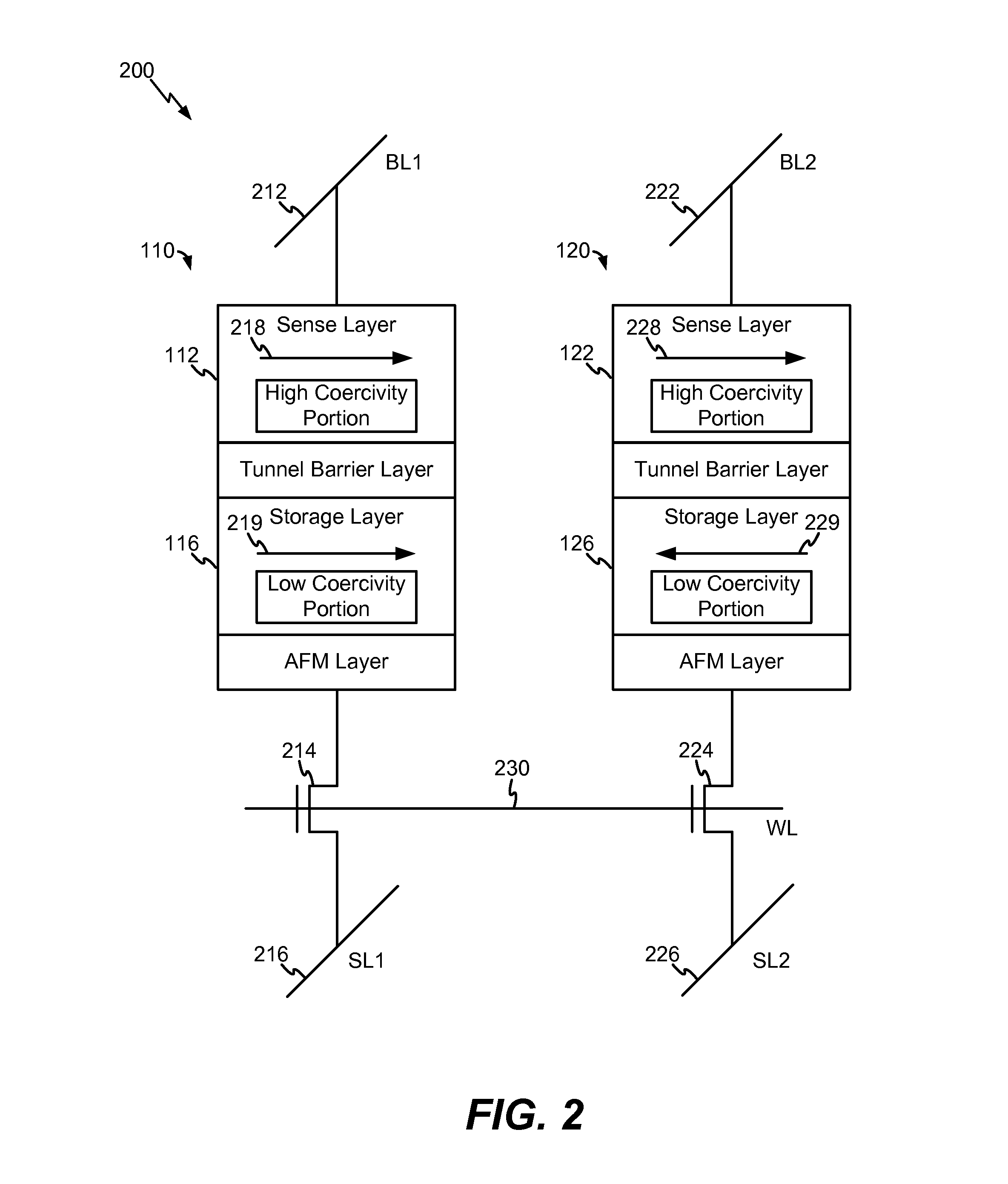
[0022]FIG. 1 illustrates a differential magnetic tunnel junction (MTJ) pair 100. The differential MTJ pair 100 includes an MTJ device 110 and an MTJ device 120. The MTJ device 110 includes a sense layer 112, a tunnel barrier layer 114, a storage layer 116, and an antiferromagnetic (AFM) layer 118. The MTJ device 120 includes a sense layer 122, a tunnel barrier layer 124, a storage layer 126, and an AFM layer 128.

[0023]The sense layers 112, 122 may have “fixed” magnetic states having a common (e.g., parallel) orientation. For example, the sense layers 112, 122 may include “hard” magnetic materials, such as high coercivity portions 111, 121. In an illustrative example, the high coercivity portions 111, 121 each have a coercivity of greater than 1000 oersted (Oe). In an illustrative implementation, the high coercivity portions 111, 121 include a cobalt / iron / boron (Co / Fe / B) material, such a cobalt-iron alloy doped with boron. A Co / Fe / B material may have a coercivity of between 2000-3000...


PUM


Abstract

An apparatus includes a first magnetic tunnel junction (MTJ) device of a differential MTJ pair. The apparatus further includes a second MTJ device of the differential MTJ pair. The first MTJ device includes a sense layer having a high coercivity portion.

Description

I. FIELD[0001]The present disclosure is generally related to memory devices and more particularly to magnetoresistive memory devices.II. DESCRIPTION OF RELATED ART[0002]An electronic device may include a memory that stores information, such as instructions, user data, and other information. For example, an electronic device may include a magnetoresistive random access memory (MRAM) device. An MRAM device may include multiple magnetic tunnel junction (MTJ) elements, each having a state (e.g., a magnetoresistance) that can be adjusted. The state may be adjusted by applying a current through the MTJ to modify a magnetic property of the MTJ.[0003]In certain applications, an MTJ may have a reference configuration that provides a reference magnetic orientation of the MTJ. For example, a spin-torque transfer MRAM (STT-MRAM) device may include an MTJ having a storage layer, a reference layer having a fixed magnetic orientation, and a tunnel barrier between the storage layer and the referenc...

Claims


Application Information

Patent Timeline
Patent Type & Authority Applications(United States)
IPC IPC(8): G11C11/16
CPCG11C11/161G11C11/1673G11C11/16G11C11/1659G11C11/1695G11C11/165G11C11/1675G11C7/24G11C2213/78G11C11/1655H10B61/22
Inventor LU, YUKANG, SEUNG HYUK
Owner QUALCOMM INC
Why Eureka
Try Eureka