Multilayer ceramic capacitor
a ceramic capacitor and multi-layer technology, applied in the direction of fixed capacitors, stacked capacitors, fixed capacitor details, etc., can solve the problems of cracks and cracks (delamination), and achieve the effect of reducing or preventing cracks
- Summary
- Abstract
- Description
- Claims
- Application Information
AI Technical Summary
Benefits of technology
Problems solved by technology
Method used
Image
Examples
first preferred embodiment
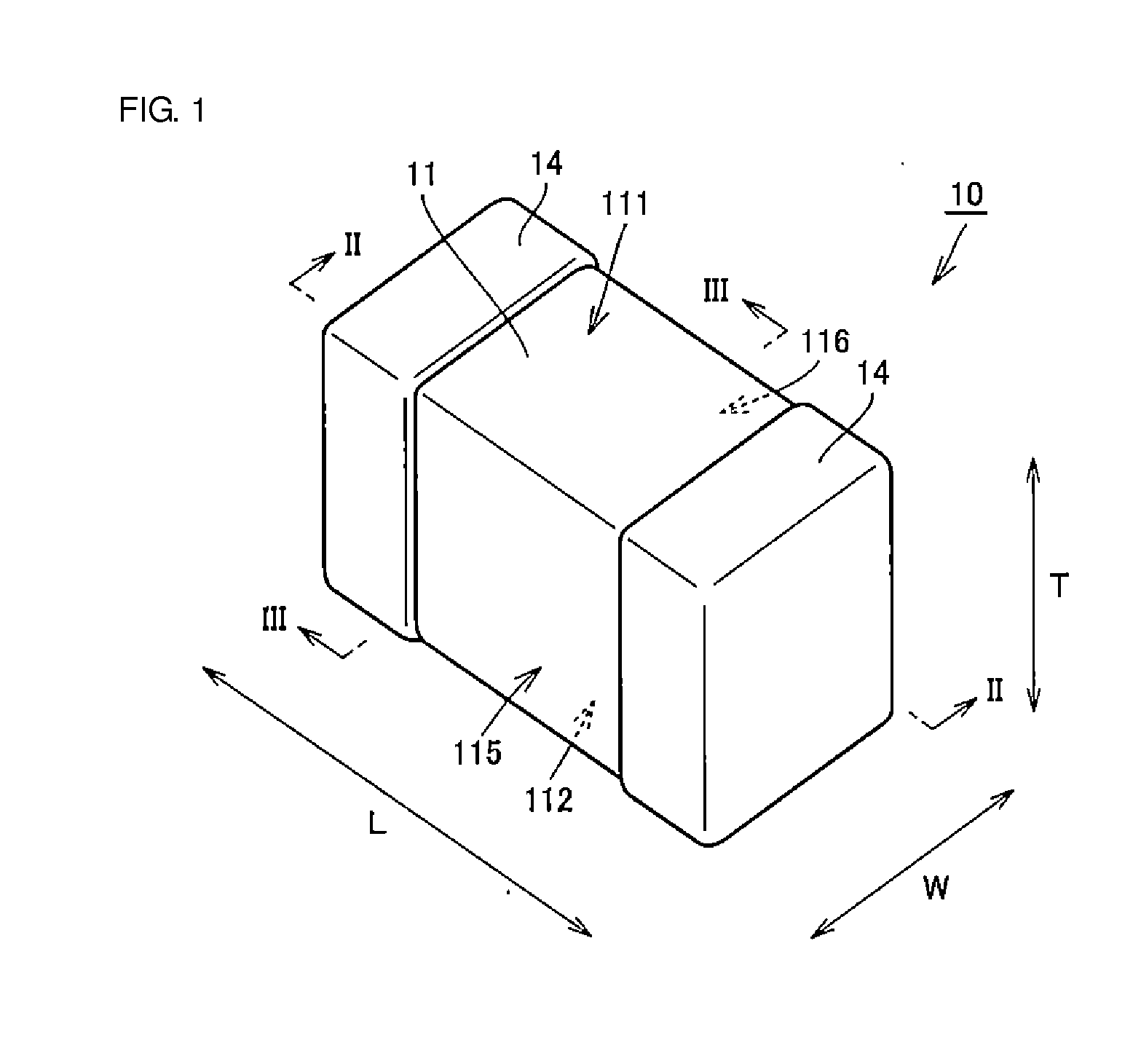
[0026]A capacitor 10 according to a first preferred embodiment of the present invention will be described below with reference to FIGS. 1 through 5.
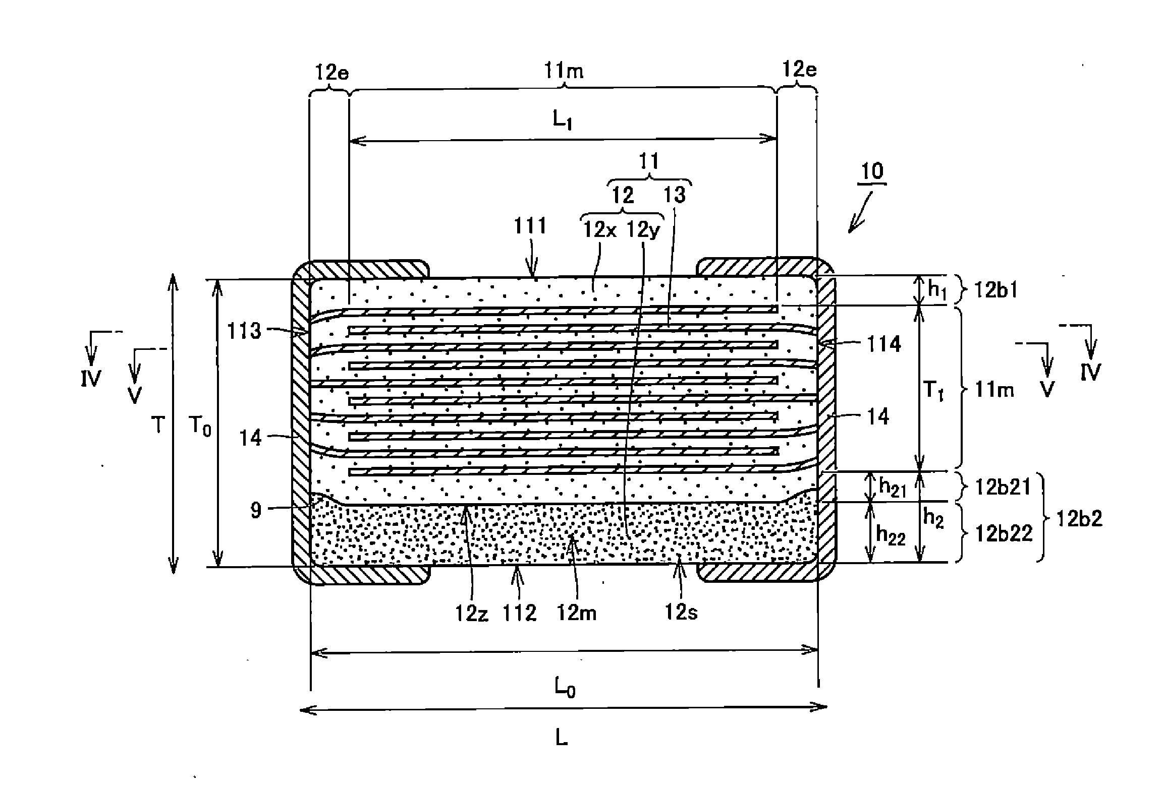
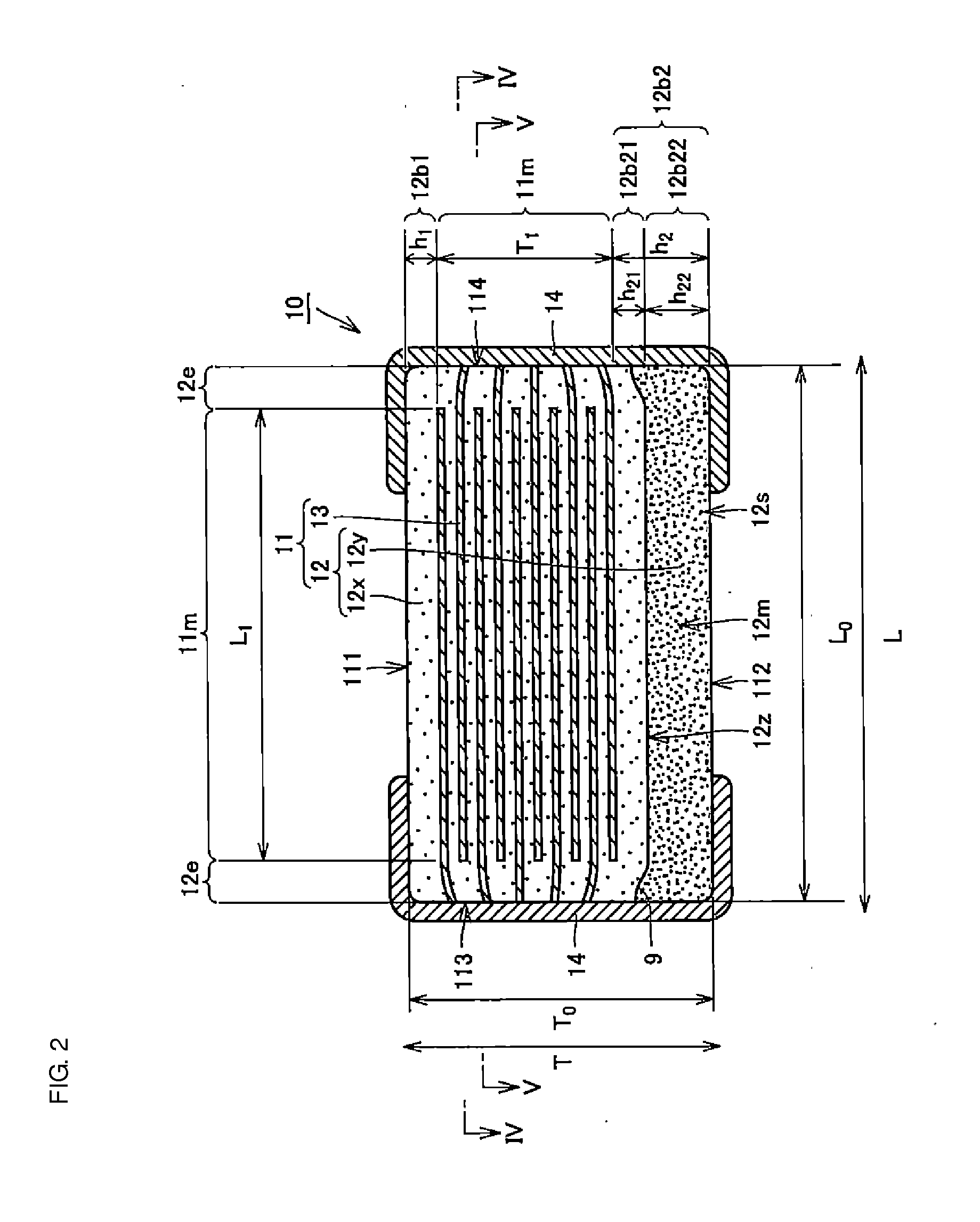
[0027]FIG. 1 is an external perspective view of the capacitor 10. FIGS. 2 and 3 are sectional views taken along lines II-II and III-III, respectively, of FIG. 1. FIGS. 4 and 5 are sectional views taken along lines IV-IV and V-V, respectively, of FIG. 2. In FIGS. 1 through 5, the length direction of a body 11, which will be discussed below, is indicated by L, the width direction thereof is indicated by W, and the height direction thereof is indicated by T.
[0028]The stacking direction of dielectric layers 12 and conductive layers 13 is perpendicular to the length direction L and the width direction W of the body 11. That is, the stacking direction of the dielectric layers 12 and the conductive layers 13 is parallel with the height direction T of the body 11.
[0029]The capacitor 10 includes the body 11 and two outer electrodes 14. The body 1...
modified example
[0044]More preferably, instead of the capacitor 10, a capacitor 10i configured as shown in FIG. 6A is used. That is, it is preferable that, as viewed from the width direction, the points of the boundary region 12z which reach the end surfaces 113 and 114 belong to a region where the inner layer portion 11m is projected toward the end surfaces 113 and 114. That is, as shown in FIG. 6A, the positions at which both ends of the boundary region 12z are in contact with the first and second end surfaces 113 and 114 are closer to the first main surface 111 than the second outermost conductive layer 13 is. In other words, in a cross section perpendicular to a direction in which the first and second side surfaces 115 and 116 are connected to each other (in particular, a cross section passing through the center of the body 11), the distance between the points of the boundary region 12z which reach the first and second end surfaces 113 and 114 and the second main surface 112 is greater than the...
second preferred embodiment
[0066]A manufacturing method for a capacitor according to a second preferred embodiment of the present invention will be described below with reference to FIGS. 7 through 10. The manufacturing method of the second preferred embodiment is a method for manufacturing the capacitor 10 discussed in the first preferred embodiment.
[0067]FIG. 7 is a flowchart illustrating a manufacturing method for the capacitor 10 in the second preferred embodiment. In this manufacturing method, a plurality of capacitors 10 are mass-produced at one time together in the following manner. Elements which will form a plurality of capacitors 10 are processed together until a halfway point through a manufacturing process so as to fabricate a mother body. Then, the mother body is divided into individual flexible bodies. The individual flexible bodies are then processed, thus manufacturing a plurality of capacitors 10.
[0068]The manufacturing method will be discussed below more specifically with reference to FIG. 7...
PUM
| Property | Measurement | Unit |
|---|---|---|
| height h21 | aaaaa | aaaaa |
| height h22 | aaaaa | aaaaa |
| height h21 | aaaaa | aaaaa |
Abstract
Description
Claims
Application Information
 - R&D
- Intellectual Property
- Life Sciences
- Materials
- Tech Scout
- Unparalleled Data Quality
- Higher Quality Content
- 60% Fewer Hallucinations
Browse by: Latest US Patents, China's latest patents, Technical Efficacy Thesaurus, Application Domain, Technology Topic, Popular Technical Reports.
© 2025 PatSnap. All rights reserved.Legal|Privacy policy|Modern Slavery Act Transparency Statement|Sitemap|About US| Contact US: help@patsnap.com


