Optical Fiber System Having a Remote Power Module

Active Publication Date: 2016-02-18
NUFERN
View PDF13 Cites 0 Cited by
  • Summary
  • Abstract
  • Description
  • Claims
  • Application Information

AI Technical Summary

Benefits of technology

The present invention is about optical fiber systems that can provide powerful optical power at a remote place without needing any additional equipment like cooling, power supply, or protective equipment.

Problems solved by technology

But as power increases, so does the physical size, mass, volume and complexity of the laser itself and also that of requisite ancillary equipment such as cooling and electrical power supply.
In many applications this volume of equipment can hinder deployment, as space at or near the point of laser use is often limited and / or expensive.
In some instances, the environment at the point of use can also be hostile, requiring further bulk and complexity resulting from additional protective equipment such as shielding, hermetic containers, and EMI and ESD protection.
But this method of beam delivery is not suitable for propagating high brightness or near diffraction limited beams.
High brightness, near diffraction limited fiber beam delivery is substantially limited in length by the onset of parasitic physical effects in the beam delivery fiber itself, for example, Brillouin backscattering and Raman wavelength shifting.
Accordingly, beam delivery fibers for high power diffraction limited fiber lasers are often limited to about 1 meter in length or less.

Method used


Image

  • Optical Fiber System Having a Remote Power Module
  • Optical Fiber System Having a Remote Power Module
  • Optical Fiber System Having a Remote Power Module

Examples


Embodiment Construction

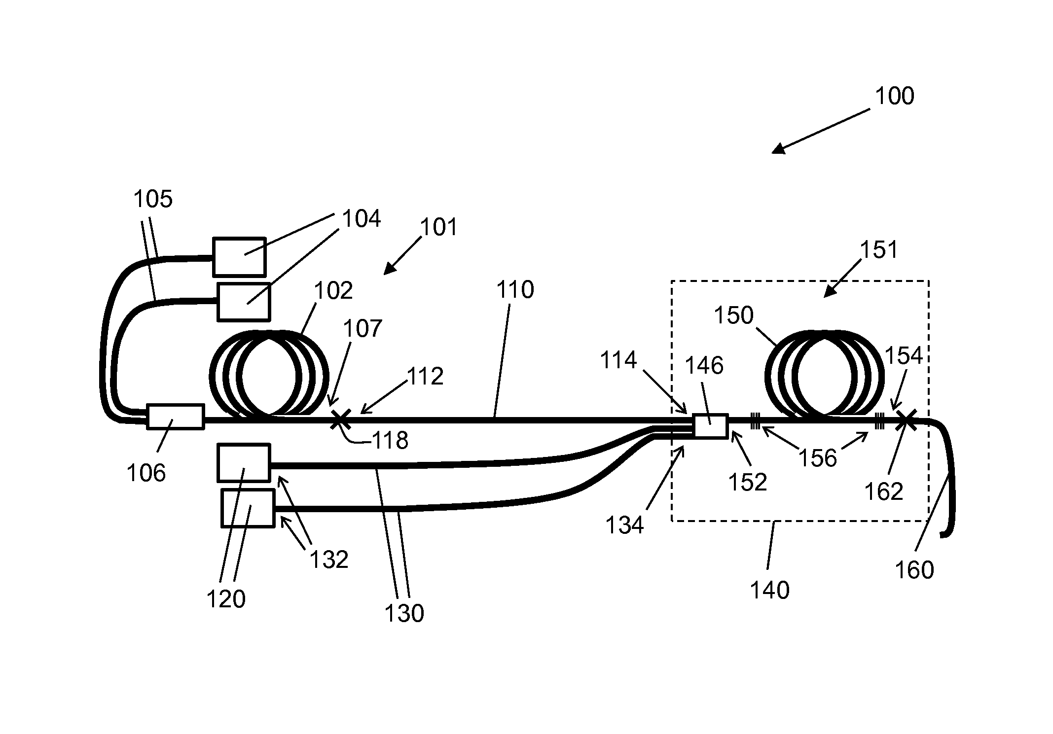
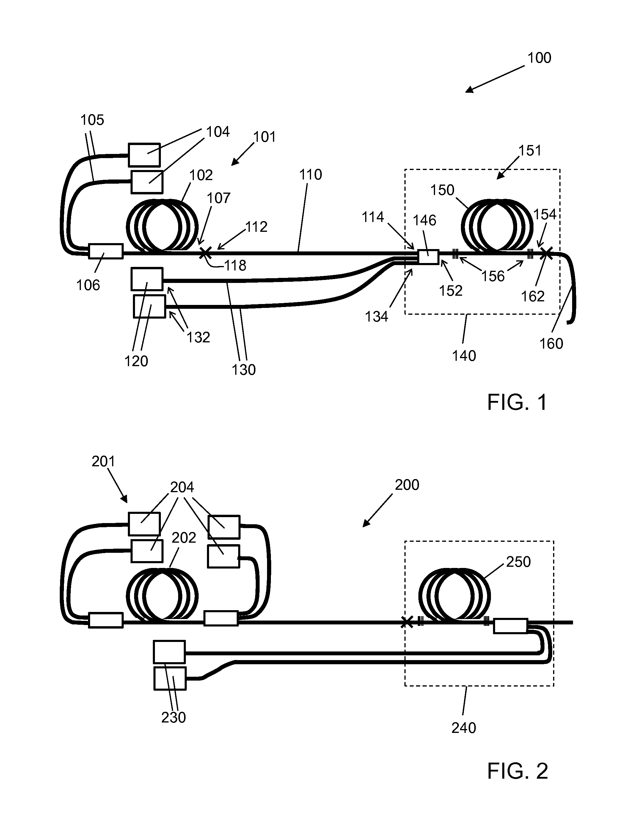
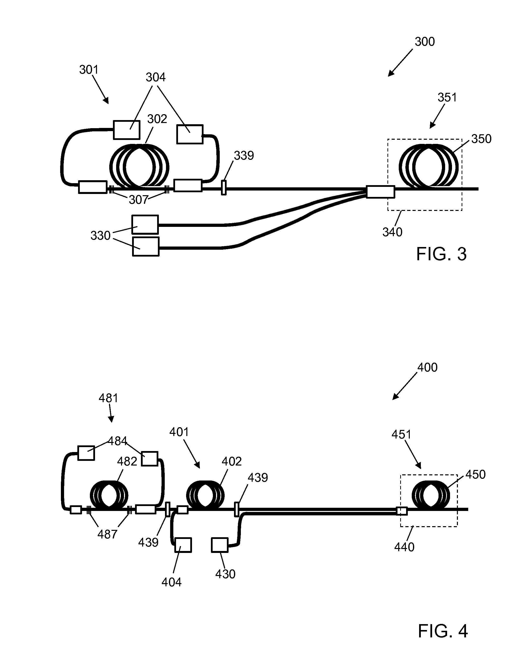
[0034]In the following discussion it is assumed that the reader has the basic knowledge of the structure of optical fibers familiar to the person of ordinary skill in the art. Thus, the concepts of a fiber core, cladding, and coating are not discussed in detail. As is familiar to the person of ordinary skill in the art, the radiation generated in an active optical fiber device, such as a fiber laser or fiber amplifier, here referred to as the signal, propagates generally in the core of the fiber, the diameter of which is typically in the range of a few microns to a few tens of microns. As used herein, the term “signal” does not imply that the radiation is encoded with any meaning; rather, it is simply the name commonly used in the optical fiber arts for radiation being transmitted by an optical fiber.

[0035]The terms “light” or “optical”, as used herein, are used broadly as understood by one of ordinary skill in the art of optical waveguides, and are not to be limited as pertaining o...


PUM

PropertyMeasurementUnit
Lengthaaaaaaaaaa
Lengthaaaaaaaaaa
Lengthaaaaaaaaaa

Abstract

The present invention relates generally to high brightness optical fiber systems and, more particularly to optical fiber systems 104 having an optical power module 151 remote from an initial amplifier stage 101. In one aspect of the invention, the optical fiber system comprises a first active optical fiber 102 operatively coupled to one or more first pump sources 104; a first signal optical fiber 110 coupled to the first active optical fiber 102; one or more final pump sources 120; one or more final pump optical fibers 130, coupled to one or more of the final pump sources 120; and spatially separated from the one or more final pump sources 120 and the initial amplifier stage 101 comprising the first active optical fiber 102, a power module 151, comprising a final active optical fiber 150, coupled to the first signal optical fiber 110, said final active optical fiber 150 being coupled to said one or more final pump optical fibers 130.

Description

CROSS-REFERENCE TO RELATED APPLICATIONS[0001]This application claims the benefit of priority of U.S. Provisional Patent Application Ser. No. 61 / 779,718, filed Mar. 13, 2013, which is hereby incorporated herein by reference in its entirety.BACKGROUND OF THE INVENTION[0002]1. Field of the Invention[0003]The present invention relates generally to optical fiber amplifiers such as optical fiber lasers. The present invention relates more particularly to optical fiber systems having an optical power head containing an amplifier stage remote from one or more initial amplifier stages.[0004]2. Technical Background[0005]Optical fiber lasers have many attractive properties that make them suitable for various industrial applications. Such properties can include one or more of good beam quality, easy thermal management, compact size, and good efficiency. Fiber lasers are therefore often preferred to conventional types of lasers, such as solid-state and gas lasers. Fiber lasers are able to produce...

Claims


Application Information

Patent Timeline
IPC IPC(8): H01S3/067H01S3/00H01S3/094H01S3/23
CPCH01S3/06758H01S3/2316H01S3/094003H01S3/0014H01S3/0675H01S3/094096H01S3/302H01S3/0064H01S3/0407H01S3/042H01S3/06704B23K26/00H01S3/067
Inventor SEIFERT, MARTINCHRISTENSEN, SCOTT
Owner NUFERN
Why Eureka
Try Eureka