Catheter, catheter manipulation part, and catheter manufacturing method

a manufacturing method and catheter technology, applied in the field of catheters, can solve the problems of large load applied to the manipulation wires, easy breakage of the manipulation wire, and plastic bending of the tubular main body

Active Publication Date: 2016-02-25
SUMITOMO BAKELITE CO LTD
View PDF3 Cites 30 Cited by
  • Summary
  • Abstract
  • Description
  • Claims
  • Application Information

AI Technical Summary

Benefits of technology

[0008]As a final step of the manufacturing of the catheter, sterilization processing is performed after both ends of the manipulation wires are fixed. Although various methods are present as the sterilization processing, a typical method is a heating and sterilizing method for replacing the air inside a sterilization bag, in which a catheter is housed, with sterilization gases, such as ethylene oxide gas, under a heating atmosphere of about 50° C. Under this heating atmosphere, the thermal expansion of the tubular main body is greater than that of the manipulation wires, and the tubular main body further elongates from a state where the manipulation wires are tightly stretched without being loosened. For this reason, tension is applied to the manipulation wires in a pulling direction, and compressive force in the direction of an axial center is applied to the tubular main body as the resistance of the tension. Here, in the case of a catheter with a relatively fine diameter, particularly, a micro catheter with a fine diameter capable of being inserted into a peripheral blood vessel as in PTL 1, the manipulation wires are very thin and the tubular main body is very flexible. For this reason, due to the thermal expansion of the catheter under the heating atmosphere, the manipulation wires easily break due to the above tension, and the tubular main body is easily bent and plastically deformed in a lateral direction due to the above compressive force.
[0010]In contrast, in the catheter of PTL 1, the position adjusting mechanism is moved backward with respect to a manipulation-part main body, so that the distal end of the tubular main body can be moved backward and the manipulation wires can be loosened. Therefore, by sufficiently moving the position adjusting mechanism backward in advance under a normal temperature atmosphere, it is possible to avoid a situation in which tension is generated in the manipulation wires even when thermal expansion of the catheter has occurred. Then, by moving the position adjusting mechanism forward when the catheter is used, the tubular main body can be moved forward with respect to the manipulation-part main body, and the loosening of the manipulation wires can be removed.
[0012]The invention has been made in view of the above problems, and an object thereof is to provide a high-quality catheter without damaging manipulation wires or a tubular main body under an environment of heating or swelling after the assembly of the catheter. Additionally, the invention provides a catheter manipulation part and a catheter manufacturing method together.
[0016]According to the invention, the bending manipulation part having the engagement part engaging with the base ends of the manipulation wires is provided so as to be movable with respect to the manipulation-part main body, and the path lengths of the manipulation wires from the tips thereof to the engagement part are simultaneously increased or decreased when the bending manipulation part and the manipulation-part main body move relative to each other. For this reason, by moving the bending manipulation part relative to the manipulation-part main body, the manipulation wires can be loosened or the loosening thereof can be removed. Accordingly, the problem of damage to the manipulation wires or the tubular main body resulting from heating or swelling can be solved without moving the tubular main body with respect to the manipulation-part main body or by reducing an amount by which the tubular main body is moved with respect to the manipulation-part main body.
[0017]According to the catheter, the catheter manipulation part, and the catheter manufacturing method of the invention, a high-quality catheter is provided without damaging the manipulation wires or the tubular main body under an environment of heating or swelling after the assembly of the catheter.

Problems solved by technology

For this reason, the present inventors found out that, when the heat environment or the humidity environment of the catheter fluctuates after assembling and forming of the catheter, new problems occur in that large loads are applied to the manipulation wires or the tubular main body, and the manipulation wires break or the tubular main body is plastically bent.
For this reason, due to the thermal expansion of the catheter under the heating atmosphere, the manipulation wires easily break due to the above tension, and the tubular main body is easily bent and plastically deformed in a lateral direction due to the above compressive force.
Such thermal expansion is a problem that may occur under various environments after the assembling or packaging of catheters, such as transportation environments in summer, as well as at the time of the heating and sterilization.

Method used


Image

  • Catheter, catheter manipulation part, and catheter manufacturing method
  • Catheter, catheter manipulation part, and catheter manufacturing method
  • Catheter, catheter manipulation part, and catheter manufacturing method

Examples


first embodiment

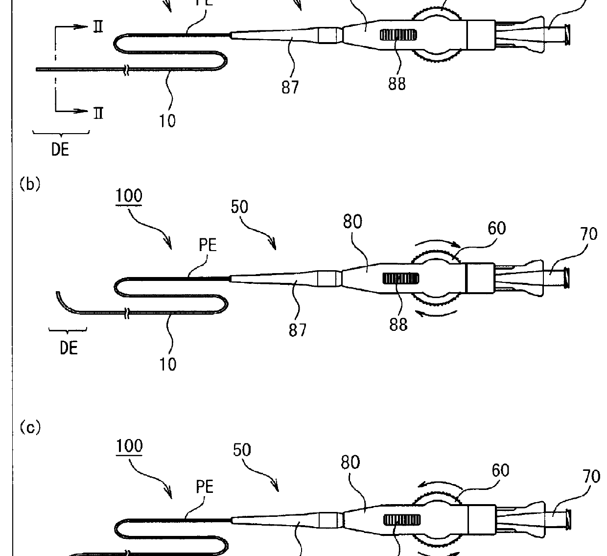
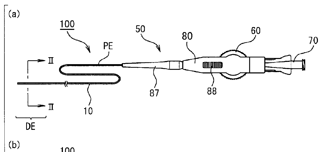
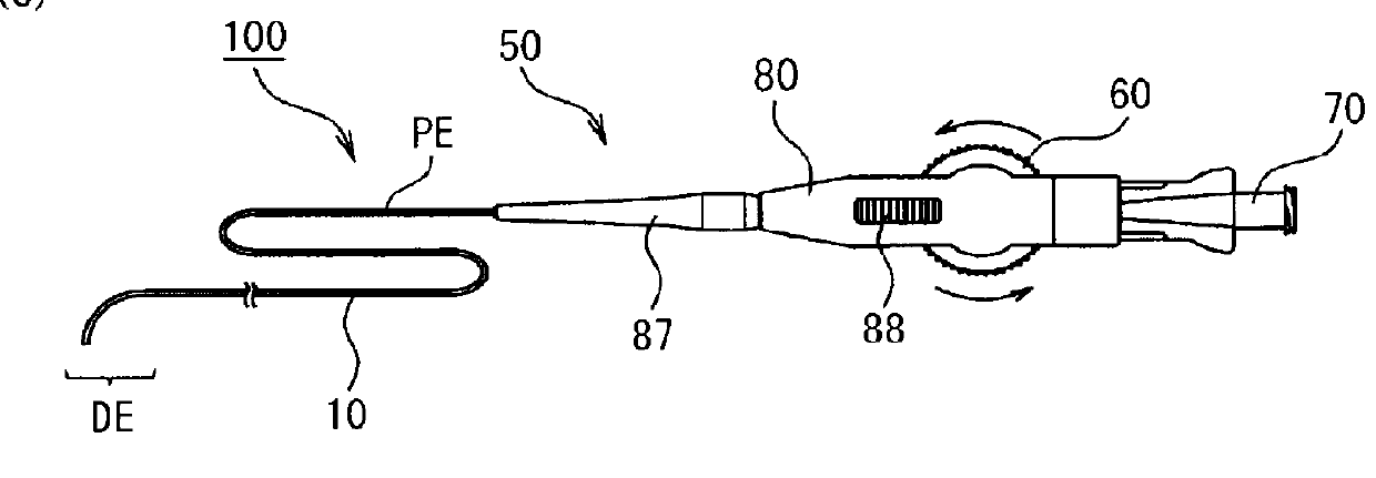
[0033]First, the outline of a catheter 100 of the present embodiment will be described. FIG. 1(a) is a plan view illustrating an overall configuration of the catheter 100 of the present embodiment. FIG. 1(b) is a plan view of the catheter 100 illustrating a state where a bending manipulation part 60 has been manipulated in one direction (in a clockwise direction in this drawing). FIG. 1(c) is a plan view of the catheter 100 illustrating a state where the bending manipulation part 60 has been manipulated in the other direction (in a counterclockwise direction in this drawing).

[0034]FIG. 2 is a cross-sectional view of the catheter 100 and is a sectional view along line II-II of FIG. 1(a).

[0035]FIG. 3 is a longitudinal sectional view of a distal part DE of the catheter 100, and is a sectional view along line of FIG. 2.

[0036]The catheter 100 includes an elongated flexible tubular main body 10, a plurality of manipulation wires 30a and 30b that are inserted through the tubular main body ...

second embodiment

[0141]FIGS. 14(a) and 14(b) are longitudinal sectional views illustrating the internal structure of the manipulation part 50 of a second embodiment of the invention. FIG. 14(a) illustrates a retracted state, and FIG. 14(b) illustrates a manipulated state. The illustration of the reinforcing member 90 and the hub connector 70 are omitted.

[0142]The manipulation part 50 of the present embodiment is different from the first embodiment in that the bending manipulation part 60 has a plurality of sliding parts 110 and 120 that individually move forward and backward with respect to the manipulation-part main body 80.

[0143]The base ends of the plurality of manipulation wires 30a and 30b engage with the sliding parts 110 and 120, respectively. Then, the plurality of sliding parts 110 and 120 are integrally moved by causing the bending manipulation part 60 to transit from the retracted position to the manipulation position.

[0144]The sliding parts 110 and 120 are individually provided to face t...


PUM


Abstract

A catheter of the invention includes an elongated flexible tubular main body; a plurality of manipulation wires inserted through the tubular main body and having tips connected to a distal part of the tubular main body; a manipulation-part main body provided at a base end of the tubular main body; and a bending manipulation part. The bending manipulation part has an engagement part engaging with base ends of the manipulation wires, and individually applies pulling force to the plurality of manipulation wires through pulling operations so as to bend the distal part of the tubular main body. The bending manipulation part is provided so as to be movable with respect to the manipulation-part main body. The path lengths of the plurality of manipulation wires from the tips thereof to the engagement part are simultaneously increased or decreased when the bending manipulation part and the manipulation-part main body move relative to each other.

Description

TECHNICAL FIELD[0001]The present invention relates to a catheter, a catheter manipulation part, and a catheter manufacturing method.[0002]Priority is claimed on Japanese Patent Application No. 2013-069528, filed Mar. 28, 2013, the content of which is incorporated herein by reference.BACKGROUND ART[0003]Catheters capable of pulling manipulation wires to perform bending manipulation of a distal part have been suggested. It is possible to bend the distal part bent inside a body cavity or at a branch point, thereby selecting an insertion direction.[0004]PTL 1 discloses a catheter including a manipulating mechanism referred to as a dial part. Two manipulation wires branching from a tubular main body are mounted around the dial part in opposite directions and fixed thereto. The tubular main body (sheath) of the catheter is pulled out to a base end side of a manipulation-part main body through a lower part of the dial part, and a position adjusting mechanism and a hub connector are provide...

Claims


Application Information

Patent Timeline
Patent Type & Authority Applications(United States)
IPC IPC(8): A61M25/01A61M25/00B65B55/14
CPCA61M25/0136A61M25/0147A61M25/0097B65B55/14A61M25/0009
Inventor KANEMASA, KENICHIHARATA, SHINETSUABE, YOSHIHIROTANAKA, HAYAOIKEDA, MASAOKAMADA, KEIJI
Owner SUMITOMO BAKELITE CO LTD
Why Eureka
Try Eureka