Radial or mixed-flow compressor diffuser having vanes

Active Publication Date: 2016-02-25
SAFRAN HELICOPTER ENGINES
View PDF5 Cites 16 Cited by
  • Summary
  • Abstract
  • Description
  • Claims
  • Application Information

AI Technical Summary

Benefits of technology

[0012]In particular, the invention has the objective of proposing a diffuser for a radial or mixed-flow compressor capable of limiting the isentropic efficiency drop of the

Problems solved by technology

However, deflection of the air flow leaving the wheel by the vanes of the diffuser can cause separation of the fluid on the intrados or the extrados of the vanes, which separation, if it is considerable, can lead to stalling of the fluid and, as a result, of pumping.
It is known that this pumping phenomenon is harmful to the elements constituting the compressor, so that one seeks to avoid it to the extent possible.
However, these vanes have a limitation in terms

Method used


Image

  • Radial or mixed-flow compressor diffuser having vanes
  • Radial or mixed-flow compressor diffuser having vanes
  • Radial or mixed-flow compressor diffuser having vanes

Examples


Example

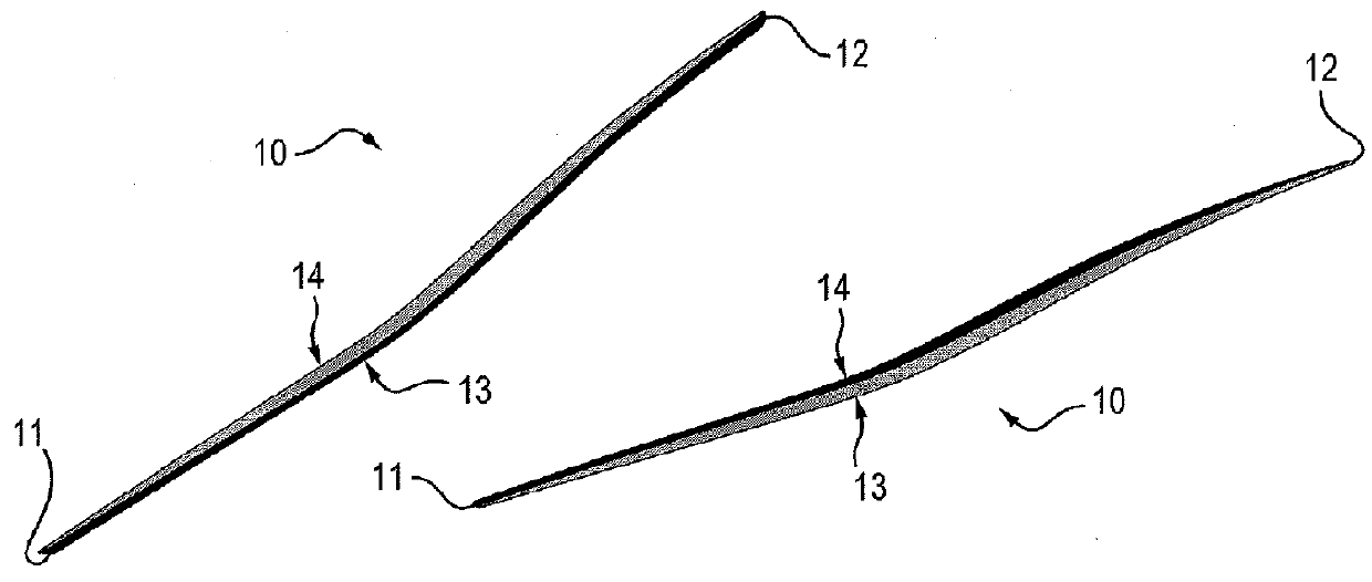
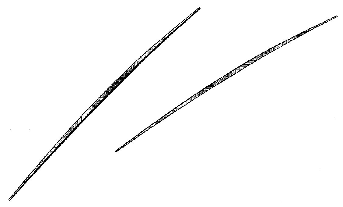
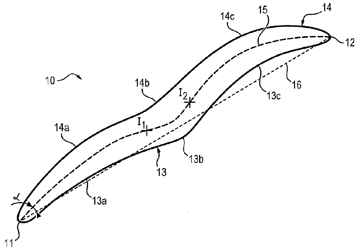
[0021]A radial diffuser according to the present invention is in particular designed to be used with a radial or mixed-flow compressor 2.

[0022]FIG. 4 is a partial section of an engine 1 comprising a radial compressor 2. A gas flow F is first aspirated into an air entry channel, then compressed between the blades 3a of a wheel 3 of the radial compressor 2 and its casing. The compressor 2 has axial symmetry about an axis X. The compressed gas flow F then exits radially from the wheel 3. If the compressor 2 were of mixed-flow type, the gas flow would exit inclined at a nonzero angle with respect to a direction radial to axis X.

[0023]The compressed air exits the wheel 3 radially while still having angular momentum, and passes into diffuser 5. The role of the diffuser is to convert part of the kinetic energy of the gases coming from the compressor 2 into static pressure by slowing the speed of the gases, and to straighten the flow exiting the wheel 3. It includes for this purpose a plura...


PUM


Abstract

The invention relates to a vane (10) of a diffuser (5) for a radial or mixed-flow compressor (2) of an engine (1), including a leading edge (11) arranged facing a flow of gas, a trailing edge (12) being opposite the leading edge (11), a side upper surface wall (13) and a side lower surface wall (14) which connect the leading edge (11) to the trailing edge (12), and a profile including a curved line (15) having at least two points of inflection (I1, I2) between the leading edge (11) and the trailing edge (12). The invention also relates to a corresponding radial diffuser (2).

Description

FIELD OF THE INVENTION[0001]The invention relates generally to gas turbine engines, and more particularly to a diffusion stage of a radial or mixed-flow compressor of a gas turbine, as well as to an associated compressor.TECHNOLOGICAL BACKGROUND[0002]A compressor includes one or more rotating discs (rotor or wheel), bladed or not, and one or more wheels with fixed vanes (straightener stages).[0003]A radial (or centrifugal) compressor has at least one radial compressor stage, that is capable of achieving a flow of gas perpendicular to the central axis of the compressor. It includes at least one wheel with radial blades which aspirate the air axially which, under the influence of the radial force, is accelerated, compressed and driven out radially. This air is then straightened in a diffuser (fixed vanes) which transforms part of its speed into static pressure by slowing the gases leaving the wheel. The operation must take place with a minimum of total pressure loss while still mainta...

Claims


Application Information

Patent Timeline
IPC IPC(8): F04D29/44F04D17/12
CPCF04D17/12F04D29/444F05D2250/52F04D29/44
Inventor TARNOWSKI, LAURENTBULOT, NICOLAS PASCAL
Owner SAFRAN HELICOPTER ENGINES
Why Eureka
Try Eureka