Branch prediction using least-recently-used (LRU)-class linked list branch predictors, and related circuits, methods, and computer-readable media

a branch predictor and branch technology, applied in the field of branch prediction, can solve the problems of reducing processor performance, increasing power consumption, and affecting the performance of the execution pipelin

Inactive Publication Date: 2016-02-25
QUALCOMM INC
View PDF7 Cites 41 Cited by
  • Summary
  • Abstract
  • Description
  • Claims
  • Application Information

AI Technical Summary

Benefits of technology

[0012]In another aspect, a non-transitory computer-readable medium is provided, having stored thereon computer executable instructions to cause a processor to detect a first branch instruction corresponding to a subroutine call in an instruction stream. The computer-executable instructions further cause the processor to determine whether the first branch instruction is predicted to be taken. The computer-executable instructions also cause the processor to, responsive to determining that the first branch instruction is predicted to be t

Problems solved by technology

However, concurrent execution of instructions in an execution pipeline may be hampered by the presence of conditional branch instructions.
As a result, the processor may have to stall the fetching of additional instructions until a conditional branch instruction has executed, resulting in reduced processor performance and increased power consumption.
However, conventional stack-based branch predictors are susceptible to corruption arising from speculative call and return branches.
If, at this point, it is determined that the execution flow within subroutine

Method used


Image

  • Branch prediction using least-recently-used (LRU)-class linked list branch predictors, and related circuits, methods, and computer-readable media
  • Branch prediction using least-recently-used (LRU)-class linked list branch predictors, and related circuits, methods, and computer-readable media
  • Branch prediction using least-recently-used (LRU)-class linked list branch predictors, and related circuits, methods, and computer-readable media

Examples


Embodiment Construction

[0023]With reference now to the drawing figures, several exemplary aspects of the present disclosure are described. The word “exemplary” is used herein to mean “serving as an example, instance, or illustration.” Any aspect described herein as “exemplary” is not necessarily to be construed as preferred or advantageous over other aspects.

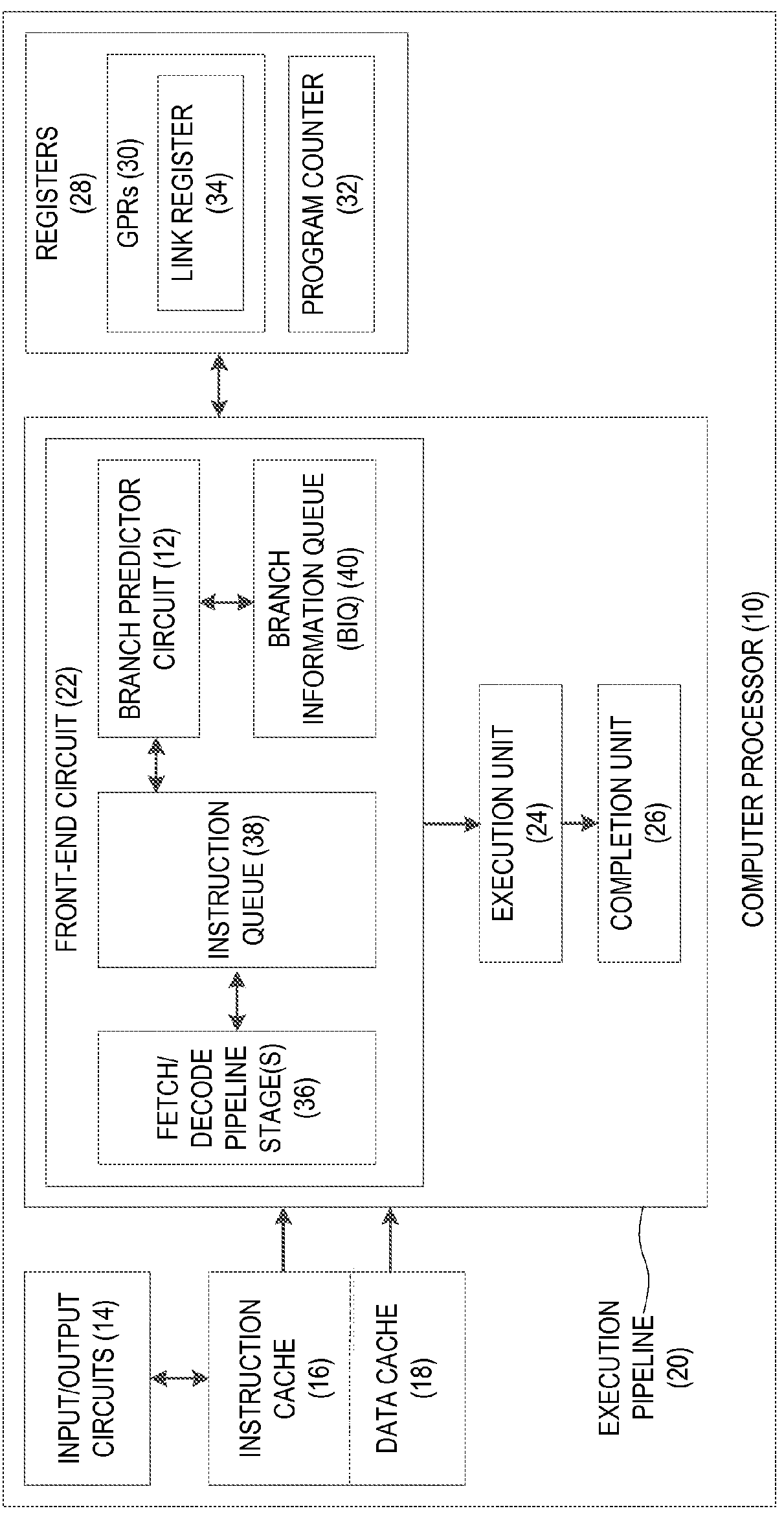
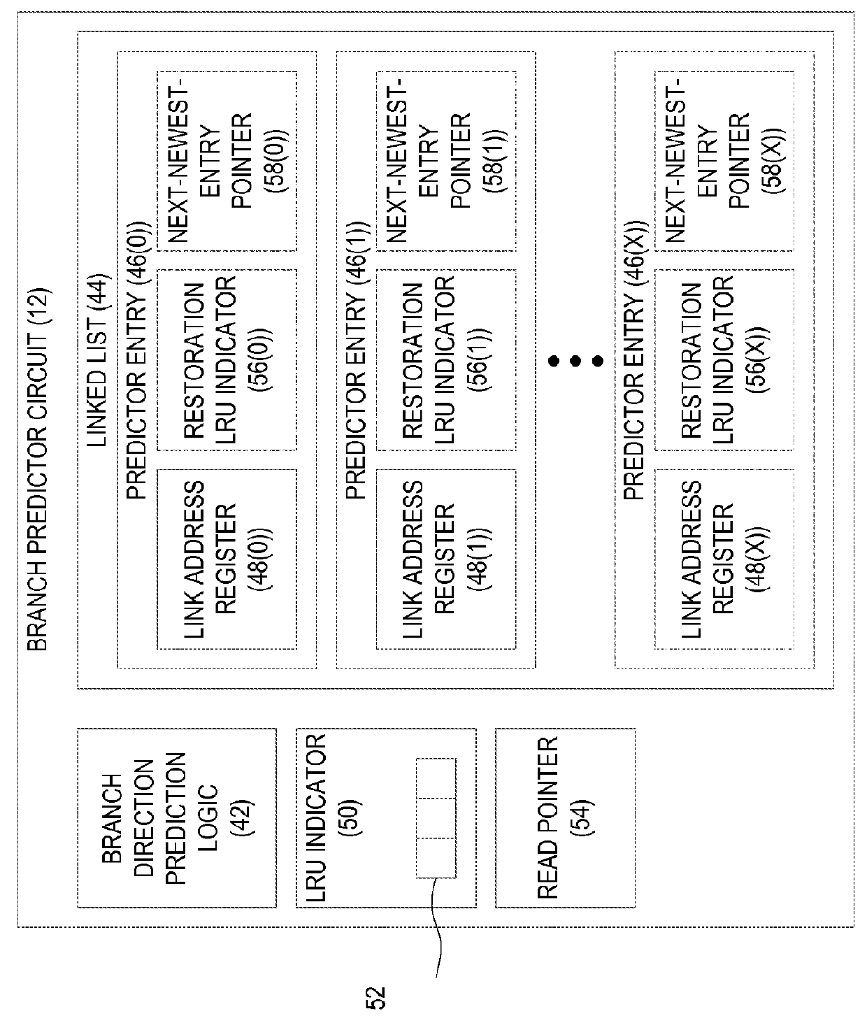
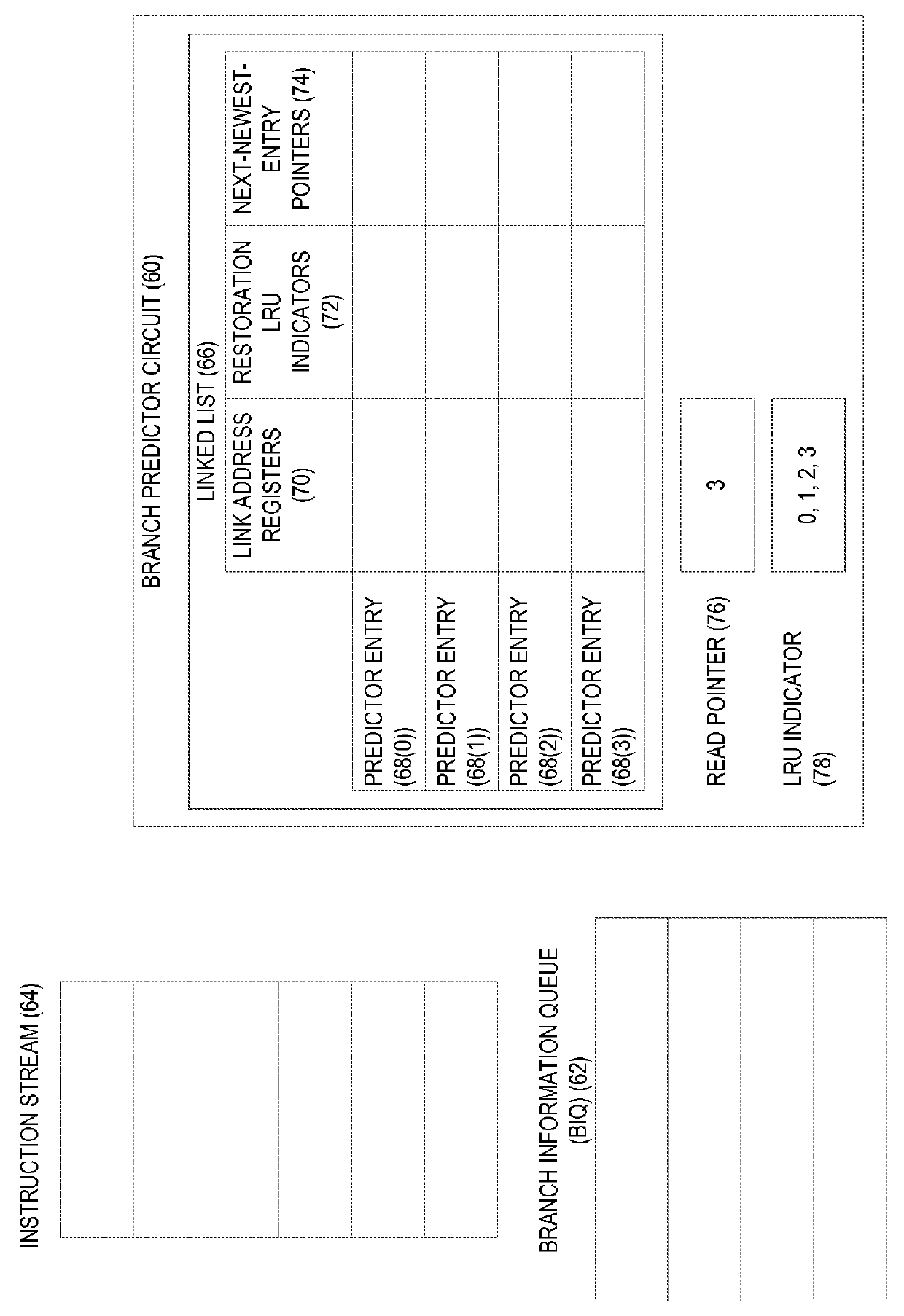
[0024]Aspects disclosed in the detailed description include branch prediction based on Least-Recently-Used (LRU)-class linked list branch predictors. Related apparatus, methods, and computer-readable media are also disclosed. As used herein, “LRU-class” and “LRU indicator” refer to the use of a replacement policy (such as Least-Recently-Used or Pseudo-Least-Recently-Used, as non-limiting examples) that is premised upon allocating least-recently-used predictor entries rather than a most-recently-used predictor entry. In this regard, a branch predictor circuit is provided. The branch predictor circuit comprises branch direction prediction logic, and fur...


PUM


Abstract

Branch prediction using Least-Recently-Used (LRU)-class linked list branch predictors, and related circuits, methods, and computer-readable media are disclosed. In one aspect, a branch predictor circuit comprises branch direction prediction logic and a linked list comprising a plurality of predictor entries, each comprising a link address register. The branch predictor circuit also comprises a LRU indicator indicative of a relative age of each of the predictor entries. The branch predictor circuit is configured to detect a first branch instruction in an instruction stream, and determine whether the first branch instruction is predicted to be taken. Responsive to determining that the first branch instruction is predicted to be taken, the branch predictor circuit allocates a least-recently-used entry of the plurality of predictor entries of the linked list based on the LRU indicator, and stores a sequential address for the first branch instruction in the link address register of the least-recently-used predictor entry.

Description

PRIORITY CLAIM[0001]The present application claims priority to U.S. Provisional Patent Application Ser. No. 62 / 038,926 filed on Aug. 19, 2014 and entitled “BRANCH PREDICTION USING PSEUDO-LEAST-RECENTLY-USED (PLRU)-BASED LINKED LIST BRANCH PREDICTORS, AND RELATED CIRCUITS, METHODS, AND COMPUTER-READABLE MEDIA,” which is incorporated herein by reference in its entirety.BACKGROUND[0002]I. Field of the Disclosure[0003]The technology of the disclosure relates generally to branch prediction for instructions executed in a pipelined computer processor.[0004]II. Background[0005]Instruction pipelining is a processing technique whereby the throughput of computer instructions being executed by a processor may be increased by splitting the handling of each instruction into a series of steps. These steps are executed in an execution pipeline composed of multiple stages. Optimal processor performance may be achieved if all stages in an execution pipeline are able to process instructions concurrent...

Claims


Application Information

Patent Timeline
IPC IPC(8): G06F9/38G06F12/08G06F12/12
CPCG06F9/3861G06F12/122G06F2212/452G06F12/0875G06F2212/69G06F9/3867G06F9/3806G06F9/3844G06F9/3863
Inventor CLANCY, ROBERT DOUGLASMCILVAINE, MICHAEL SCOTTWILLIAMS, SPENCER ELLIS
Owner QUALCOMM INC
Why Eureka
Try Eureka