Control device for a hydraulic braking system of a vehicle, hydraulic braking system for a vehicle, and method for operating a hydraulic braking system of a vehicle

Inactive Publication Date: 2016-03-03
ROBERT BOSCH GMBH
View PDF6 Cites 7 Cited by
  • Summary
  • Abstract
  • Description
  • Claims
  • Application Information

AI Technical Summary

Benefits of technology

The present invention is about a system that can brake regeneratively without leaving any residual pressure. It reduces the first and second brake pressures to below the response pressure of the brake circuit, which makes it possible to utilize the storage chamber without having to accept the disadvantage of high pressure. This increases the efficiency of the braking system and helps to reduce fuel consumption and pollutant emissions of the vehicle. The invention also allows for a heavy brake actuation for rapid charging of the vehicle battery. It does not result in the disadvantages of a brake-by-wire braking system. Overall, the invention contributes to regeneratively recovering energy during the deceleration of the vehicle and helps to improve the performance of the vehicle's energy recovery system.

Problems solved by technology

Since the first brake circuit itself is not disconnected from the master brake cylinder, and thus from the driver, even after the first changeover valve closes, the disadvantages of a complete disconnection of a brake circuit cannot occur.

Method used


Image

  • Control device for a hydraulic braking system of a vehicle, hydraulic braking system for a vehicle, and method for operating a hydraulic braking system of a vehicle
  • Control device for a hydraulic braking system of a vehicle, hydraulic braking system for a vehicle, and method for operating a hydraulic braking system of a vehicle
  • Control device for a hydraulic braking system of a vehicle, hydraulic braking system for a vehicle, and method for operating a hydraulic braking system of a vehicle

Examples


Embodiment Construction

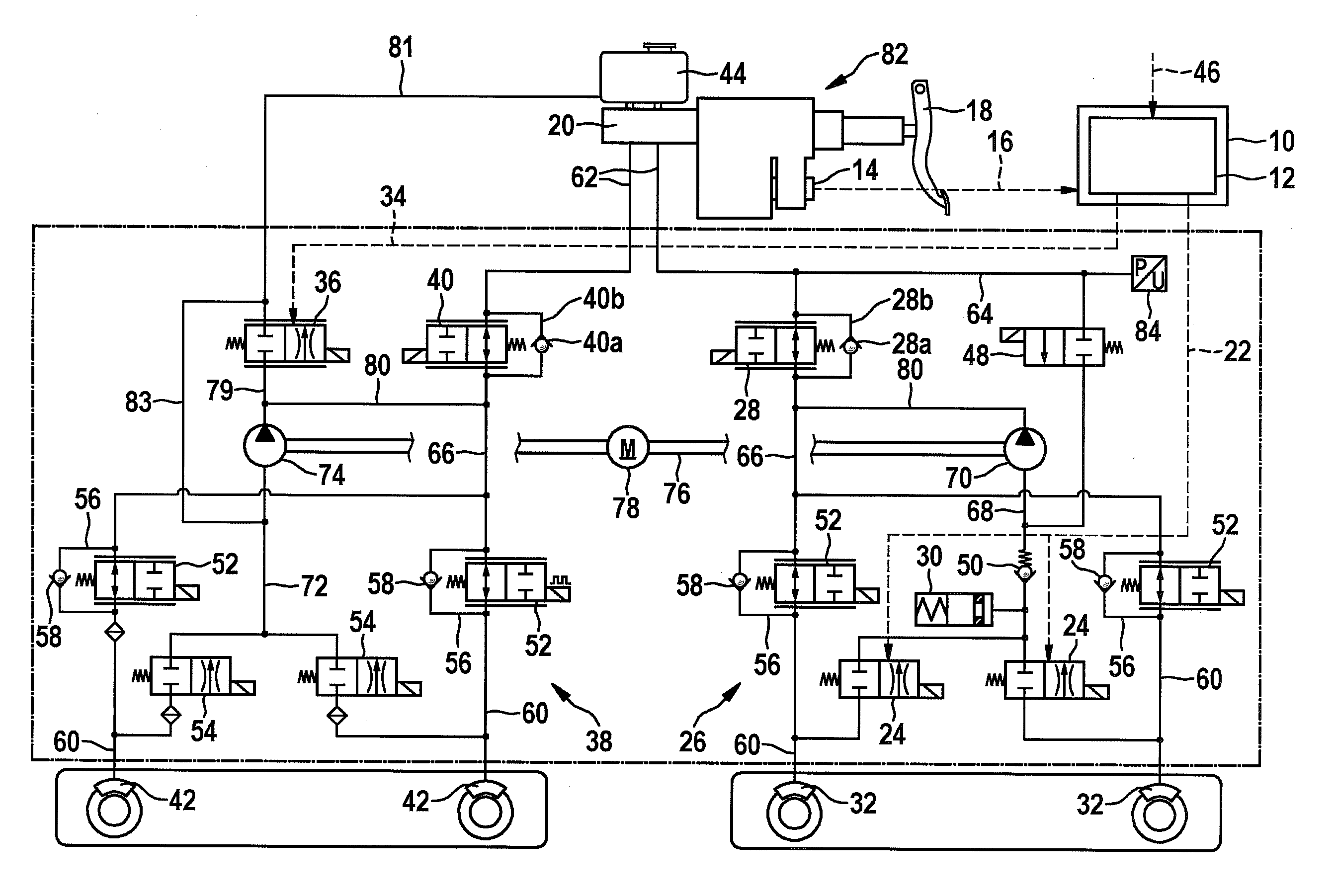
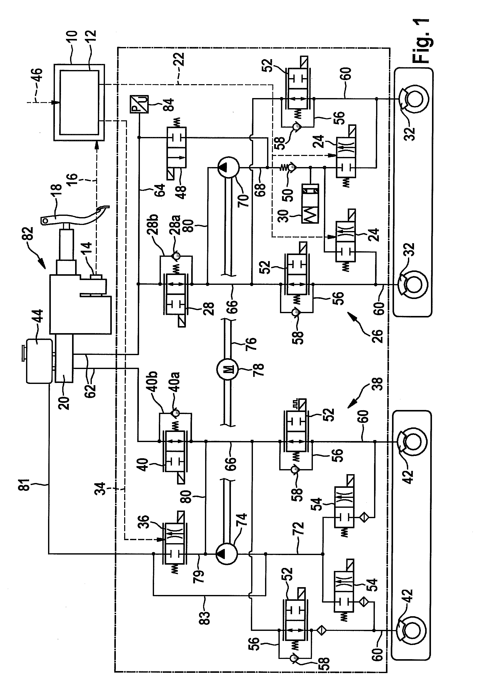
[0018]FIG. 1 shows a schematic illustration of a first specific embodiment of the control device and a braking system equipped with same.

[0019]Control device 10 schematically illustrated in FIG. 1 includes an actuating device 12 which, at least in a first operating mode, is designed for taking into account at least one sensor signal 16 provided by at least one brake actuating element sensor 14. The at least one brake actuating element sensor 14 may be, for example, a brake actuation travel sensor, such as in particular a pedal travel sensor, a differential travel sensor, and / or a rod travel sensor, a driver brake force sensor, and / or a driver brake pressure sensor. However, the design of brake actuating element sensor 14 is not limited to the types of sensors listed here. The at least one provided sensor signal 16 thus includes a piece of information concerning an activation intensity of an activation of a brake actuating element 18 of the braking system, including control device 10...


PUM


Abstract

A control device is provided for a hydraulic braking system of a vehicle, including an actuating device which is designed for outputting, at least temporarily, at least one first control signal and at least one second control signal in at least a first operating mode, taking into account at least one sensor signal. A known hydraulic braking system may be controlled with the aid of the control signals, output by the actuating device, in such a way that during an activation of a brake actuating element, at least one blending valve of a first brake circuit which is connected to the master brake cylinder via a first changeover valve is controlled into an at least partially open state in such a way that brake fluid is displaceable into at least one storage chamber, and at least one first brake pressure which is present in at least one first wheel brake cylinder of the first brake circuit is limitable, and a pressure relief valve of a second brake circuit, which is connected to the master brake cylinder via a second changeover valve, is controlled into an at least partially open state in such a way that brake fluid is displaceable into a brake fluid reservoir, and at least the first brake pressure is additionally reducible. Moreover, a hydraulic braking system is provided which includes the control device, and a method is provided for operating a hydraulic braking system.

Description

FIELD OF THE INVENTION[0001]The present invention relates to a control device for a hydraulic braking system of a vehicle. Moreover, the present invention relates to a hydraulic braking system for a vehicle. Furthermore, the present invention relates to a method for operating a hydraulic braking system of a vehicle.BACKGROUND INFORMATION[0002]Braking systems and methods for operating the braking systems are described in German Published Patent Application No. 10 2011 005 822. The braking systems in each case have a decoupleable brake circuit which is connected to a master brake cylinder via a shutoff valve. In addition, the decoupleable brake circuit is connected to a brake fluid reservoir via a pressure relief valve.SUMMARY[0003]The present invention provides a control device for a hydraulic braking system of a vehicle, a hydraulic braking system for a vehicle, and a method for operating a hydraulic braking system of a vehicle.[0004]The present invention allows a driver to brake th...

Claims


Application Information

Patent Timeline
IPC IPC(8): B60T8/40B60L7/26B60T8/48B60T13/68
CPCB60T8/4072B60T8/4872B60T13/686B60T8/4086B60L7/26
Inventor KUNZ, MICHAELJAIME, RALF-PETERSTRENGERT, STEFAN
Owner ROBERT BOSCH GMBH
Why Eureka
Try Eureka