Desalter/dehydrator system

a technology of desalter and dehydrator, which is applied in the direction of centrifuges, separation processes, filtration separation, etc., can solve the problems of corrosion in piping and machinery used in oil refining processes

Active Publication Date: 2016-03-03
FORUM US
View PDF10 Cites 6 Cited by
  • Summary
  • Abstract
  • Description
  • Claims
  • Application Information

AI Technical Summary

Problems solved by technology

Salts (such as sodium chloride, calcium chloride, magnesium chloride, etc.) which can be present in crude oil can cause corrosion in piping and machinery used in oil refining processes.

Method used


Image

  • Desalter/dehydrator system
  • Desalter/dehydrator system
  • Desalter/dehydrator system

Examples


Embodiment Construction

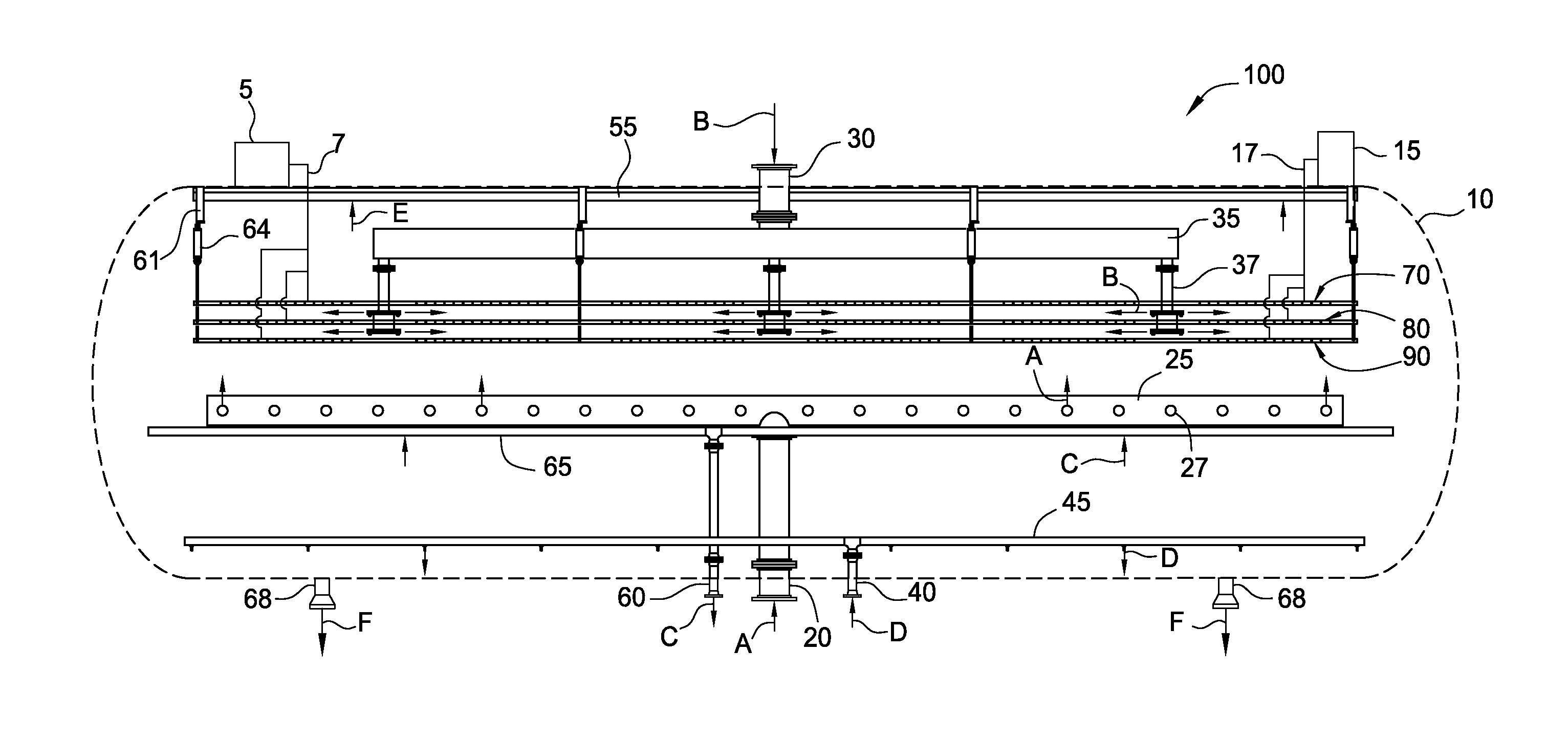
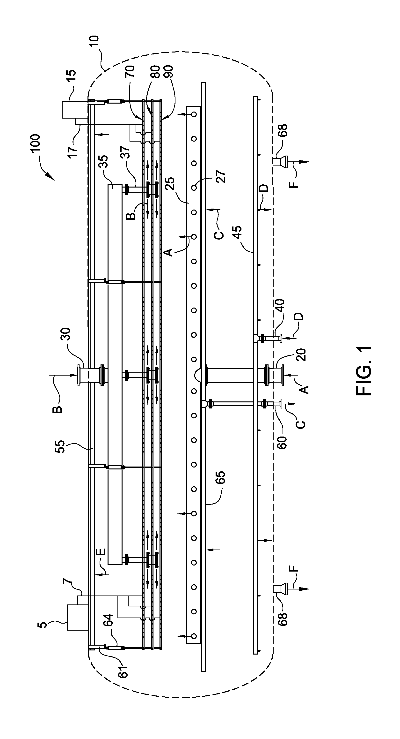
[0016]FIG. 1 illustrates a side view of a desalter / dehydrator system 100 for removing various contaminants from crude oil during an oil production / refining process, with the outer walls shown in phantom, according to one embodiment. The contaminants may include water and various salts, such salts including sodium chloride, calcium chloride, magnesium chloride, etc. If not removed from the crude oil, these contaminants can cause corrosion or other damage to the piping and machinery used in the refining or production process located fluidly downstream from the desalter / dehydrator system.

[0017]The system 100 includes a pressure vessel 10 into which an oil / water emulsion is injected. The pressure vessel 10 may comprise an elongated cylindrical housing having domed ends, although other shapes and sizes are contemplated. The pressure vessel 10 provides an enclosure for supporting the components of the system 100, headers, flanges, and related connections and openings for interconnecting t...


PUM

PropertyMeasurementUnit
droplet sizesaaaaaaaaaa
electric fieldaaaaaaaaaa

Abstract

A desalter/dehydrator system that comprises a pressure vessel, and first and second distribution headers disposed within the pressure vessel. The first distribution header is configured to inject an oil/water emulsion at a location within an electric field generated within the pressure vessel. The second distribution header is configured to inject the oil/water emulsion at a location below an electric field generated within the pressure vessel.

Description

CROSS-REFERENCE TO RELATED APPLICATION[0001]This application claims benefit of U.S. Provisional Patent Application Ser. No. 62 / 043,345 filed Aug. 28, 2015, which is incorporated herein by reference in its entirety.BACKGROUND[0002]1. Field of the Disclosure[0003]Embodiments of the present disclosure generally relate to desalter and dehydrator systems.[0004]2. Description of the Related Art[0005]Salts (such as sodium chloride, calcium chloride, magnesium chloride, etc.) which can be present in crude oil can cause corrosion in piping and machinery used in oil refining processes. Desalting of a crude oil feedstock is therefore one of the initial steps performed during an oil refining process. A desalter system is used to remove salts and other water soluble impurities contained within crude oil. A dehydrator system operates in a similar manner as a desalter system and is used to remove water contained within a crude oil feedstock to provide a dehydrated crude oil stream.[0006]Crude oil ...

Claims


Application Information

Patent Timeline
Patent Type & Authority Applications(United States)
IPC IPC(8): C10G33/02C10G31/08C10G33/08
CPCC10G33/02C10G33/08C10G31/08B01D17/06B01D17/04B03C11/00B03C2201/02
Inventor COLLINS, JR., MERLIN, THOMASBATCHELOR, JAMES, EUGENEBOUL, JONATHAN, CARTER
Owner FORUM US
Why Eureka
Try Eureka