
Single Actuator Fuel Injector for Duel Fuels

a fuel injector and actuator technology, applied in the direction of engines, mechanical equipment, machines/engines, etc., can solve the problems of diesel engines that cannot meet the performance and efficiency of currently available diesel engines, add to the capital cost of the engine and/or the operating cost, and pollute the environment,

Inactive Publication Date: 2016-03-03
CATERPILLAR INC
View PDF6 Cites 5 Cited by
  • Summary
  • Abstract
  • Description
  • Claims
  • Application Information

AI Technical Summary

Benefits of technology

The patent describes a fuel injector that can inject both liquid and gas fuels into an engine. The injector has a needle valve and a valve seat, and a delivery passage that allows the liquid fuel to flow from the control chamber to the injection chamber. The method of operation involves supplying the liquid fuel to the control chamber at a high pressure, supplying the gas fuel to the injection chamber at a lower pressure, and controlling the needle valve to control the amount of liquid fuel migration. The injector can also have a clearance space between the needle valve and the interior wall. The technical effect of this patent is to provide a fuel injector that can inject both liquid and gas fuels simultaneously, allowing for more precise control over fuel injection and improved engine performance.

Problems solved by technology

However, one disadvantage of diesel engines is pollution, such as particulate matter (soot) and NOx gases, which are subject to increasingly stringent regulations that require NOx emissions to be progressively reduced over time.
However, most of these approaches add to the capital cost of the engine and / or the operating costs.
However, this approach has been unable to match the performance and efficiency of currently available diesel engines, particularly at high gas-diesel ratios.
One problem associated with delivering two different fuels for injection directly into the combustion chambers of an internal combustion engine is the lack of physical space for two fuel injectors per cylinder and space near the fuel injectors to provide two fuel rails in addition to drain lines for taking away fuel that may leak from the injectors.
The need for two actuators per cylinder adds to the space problem.
While some fuel injectors have been proposed that are capable of injecting two different fuels, these dual fuel injectors are overly complex and expensive to build.

Method used


Image

  • Single Actuator Fuel Injector for Duel Fuels
  • Single Actuator Fuel Injector for Duel Fuels
  • Single Actuator Fuel Injector for Duel Fuels

Examples


Embodiment Construction

[0023]In this disclosure “gaseous fuel” is broadly defined as any combustible fuel that is in the gaseous phase at atmospheric pressure and ambient temperature.

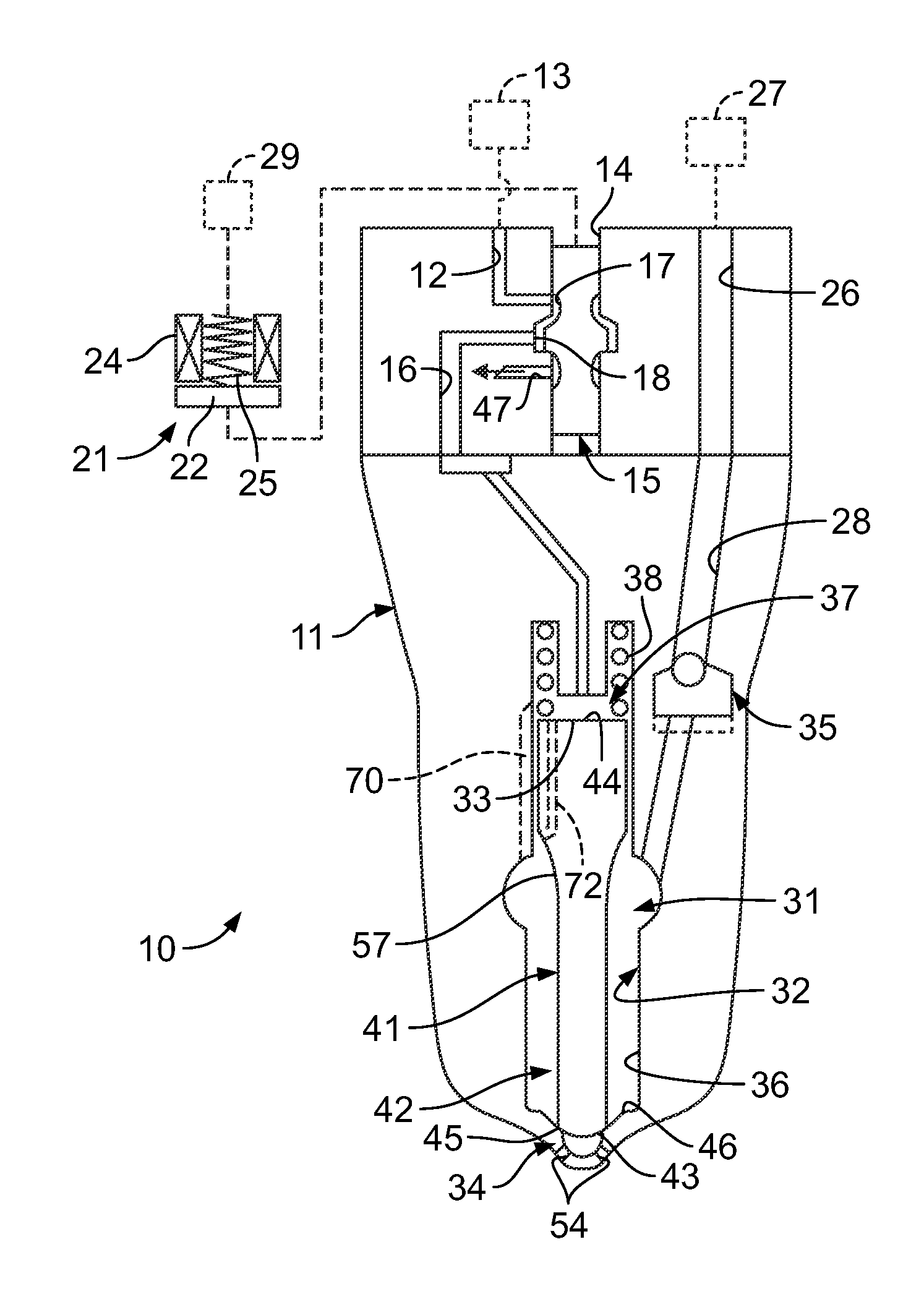
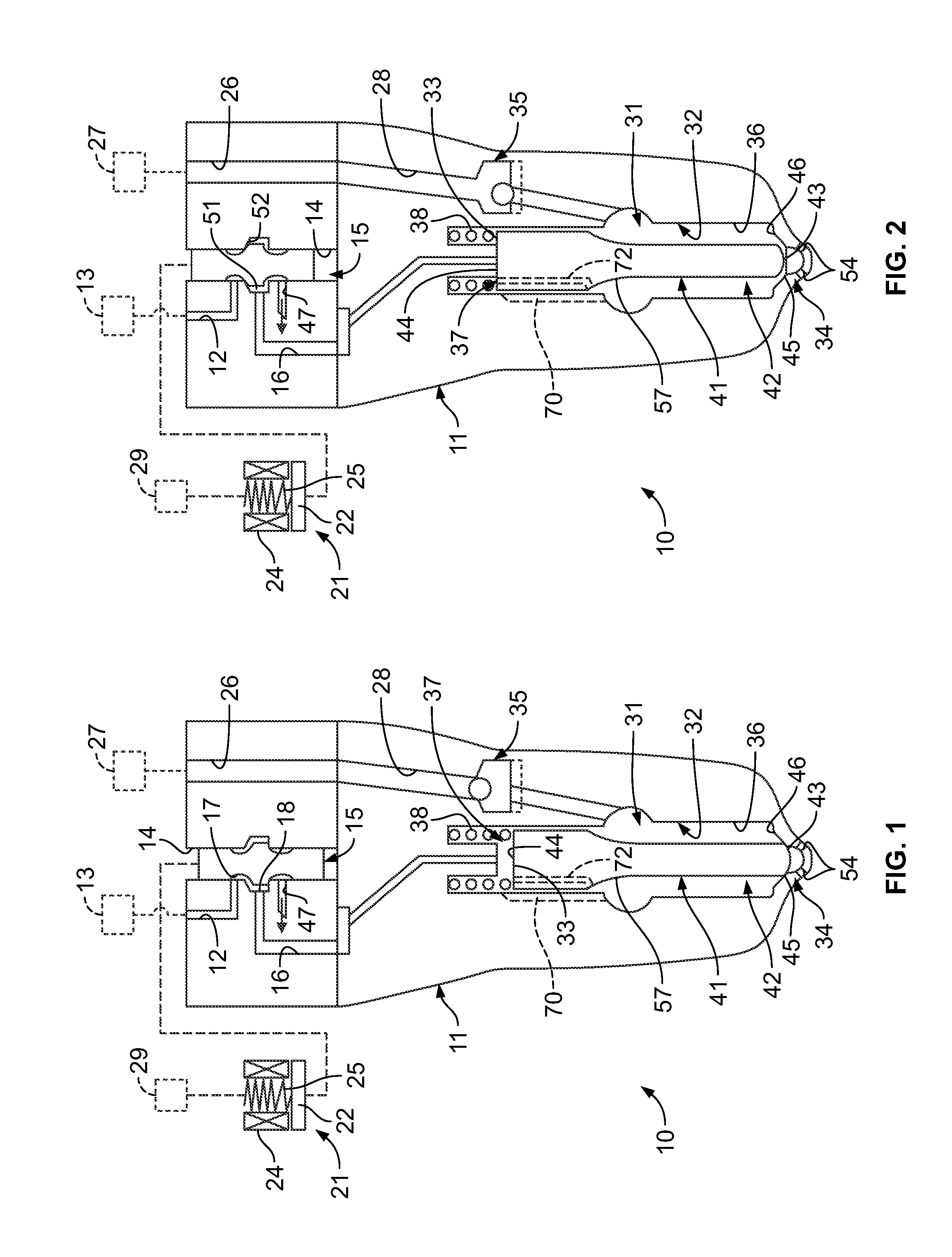
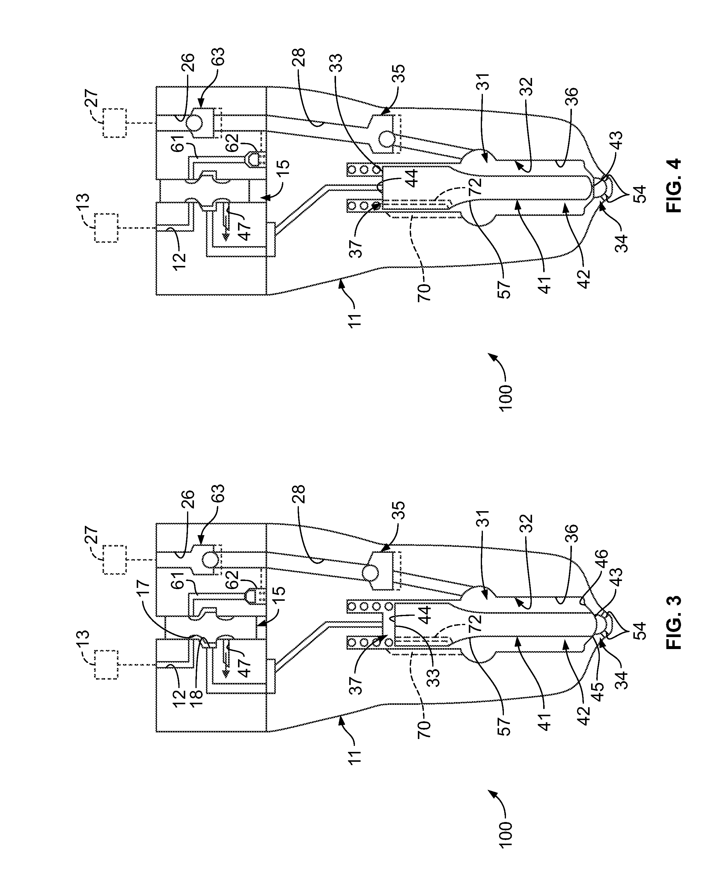
[0024]Referring now to FIG. 1, an electronically actuated fuel injector 10 includes a fuel injector body 11 that contains various moving components positioned as they would be prior to initiation of an injection event. The body 11 includes a liquid fuel inlet 12 that receives liquid fuel from a liquid fuel supply 13, such as a fuel rail, that may also include a pump (not shown) for delivering the liquid fuel to the liquid fuel inlet 12 at a predetermined pressure. For example, the liquid fuel, which may be diesel fuel, may be delivered through the liquid fuel inlet 12 at a pressure of about 40 MPa (5,802 psi), although the inlet pressure for the liquid fuel may vary widely, e.g., from about 30 MPa (4,341 psi) to about 50 MPa (7,252 psi). Thus, the liquid fuel supply 13 may include a reservoir (not shown) as well as a pump (no...


PUM


Abstract

A fuel injector concurrently injects a liquid fuel and a gaseous fuel into a combustion chamber of an internal combustion engine. An interior wall of an injector body defines a control chamber and an injection chamber. A needle valve is disposed within the body and has a control surface fluidly communicating with the control chamber. A liquid fuel inlet fluidly communicates with the control chamber and a gaseous fuel inlet fluidly communicates with the injection chamber. A delivery passage is defined by at least one of the needle valve and the interior wall and configured to place the control chamber in fluid communication with the injection chamber to permit flow of liquid fuel therebetween.

Description

TECHNICAL FIELD[0001]This disclosure relates to an apparatus and method for delivering two fuels to a direct injection internal combustion engine. More specifically, this disclosure relates to a fuel injector with a single actuator that can deliver a liquid and a gaseous fuel through an outlet nozzle to a combustion chamber.BACKGROUND[0002]Compression ignition engines, such as diesel engines, introduce fuel directly into the combustion chamber. Such engines are very efficient because they provide high compression ratios without knocking, which is the premature detonation of the fuel mixture inside the combustion chamber. Because diesel engines introduce fuel directly into the combustion chamber, the fuel injection pressure must be greater than the pressure inside the combustion chamber. For liquid fuels such as diesel, the pressure must be significantly higher so that the fuel is atomized for efficient combustion.[0003]Diesel engines are favored by industry because of their excellen...

Claims


Application Information

Patent Timeline
IPC IPC(8): F02M43/04F02M63/00
CPCF02M63/0031F02M43/04F02B7/06F02B43/00F02D19/0694F02M61/042F02M61/1806F02M63/0078Y02T10/30
Inventor COLDREN, DANA, R.
Owner CATERPILLAR INC
Learn More