
Gas well integrity inspection system

a gas well integrity and inspection system technology, applied in the direction of instruments, nuclear radiation detection, measurement devices, etc., can solve the problems of gas leakage, ground contamination, and potentially catastrophic consequences, and the ability to inspect the casing outside the innermost production casing of the gas well is a major issu

Active Publication Date: 2016-03-03
BAKER HUGHES OILFIELD OPERATIONS LLC
View PDF9 Cites 30 Cited by
  • Summary
  • Abstract
  • Description
  • Claims
  • Application Information

AI Technical Summary

Benefits of technology

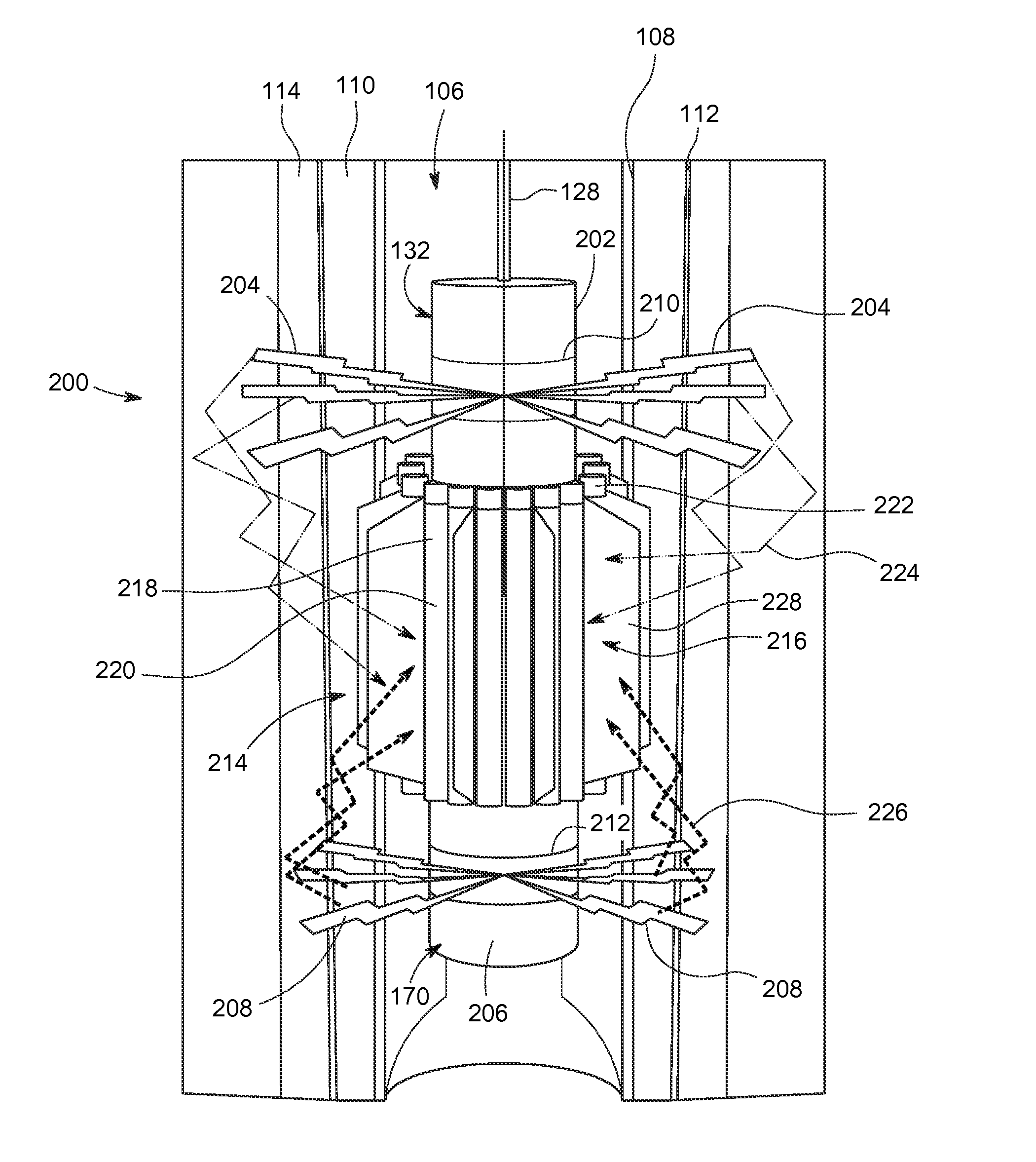
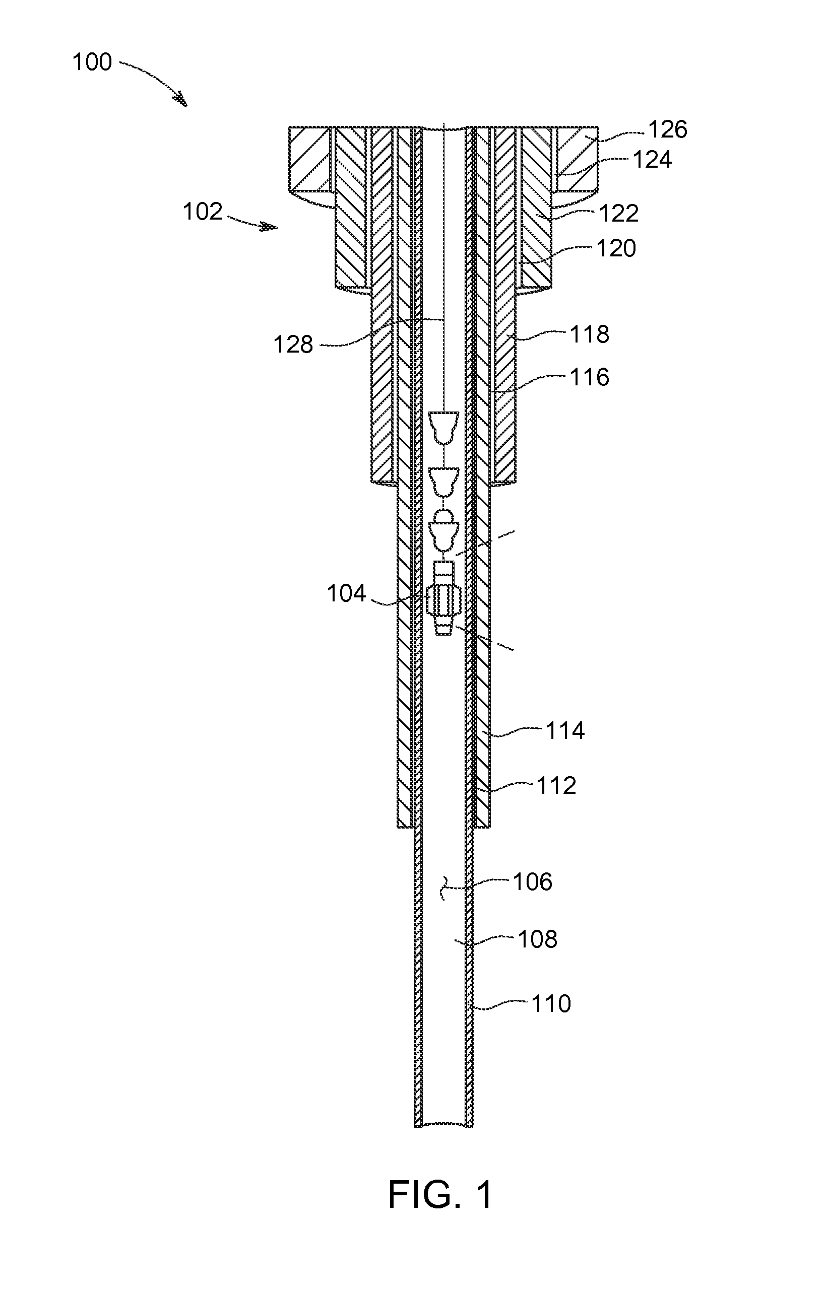
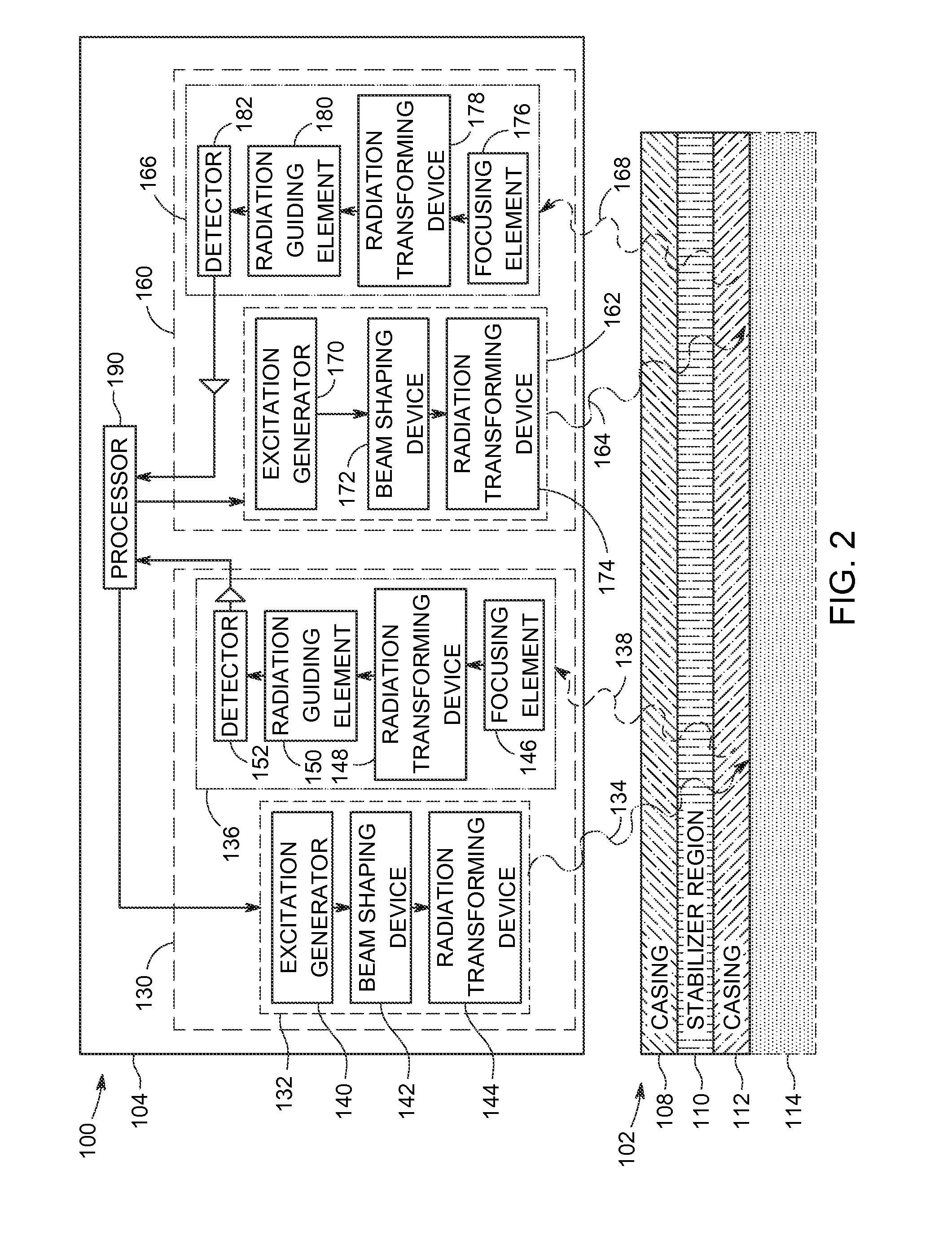
The patent describes a system and method for inspecting the integrity of a well structure with multiple layers. The system includes an inspection probe that transmits multiple radiation emissions into the well structure and receives the backscattered signals from the structure using a detection assembly. The system analyzes the signals to determine parameters such as well casing thickness and cement quality. The technical effect is an improved system for inspecting the integrity of well structures with multiple layers.

Problems solved by technology

Material degradation, defects on the installed tubular systems, shifts of ground formations, and other factors could lead to gas leakage, ground contamination, and potentially catastrophic consequences.
The ability to inspect casings outside the innermost production casing in gas wells is a major issue for the industry.
No technology currently exists that is capable of ‘seeing’ through inner casings in order to establish the integrity of the equipment outside of the wellbore.
In particular, a major technology gap exists in so far as measuring the integrity of multiple well casing and cement annuli at intermediate-to-surface depths along major aquifers and ground water zones, where cracks, corrosion, and disbonding occur.
However, this known acoustic imaging technology is not capable of inspecting multiple annuli in an intermediate zone where there are 2 to 5 stacked casing / cement rings.
Furthermore, ultrasound-based techniques do not traditionally operate in gas filled wellbores and rely on using the drilling mud as a couplant for higher frequency sound for improved resolution.
However, eddy current sensors suffer from local variations in magnetic permeability that reduce the signal-to-noise ratio and require larger sensors.
As a result, eddy current sensors have low spatial resolution.

Method used


Image

  • Gas well integrity inspection system
  • Gas well integrity inspection system
  • Gas well integrity inspection system

Examples


Embodiment Construction

[0017]In the following specification and the claims, reference will be made to a number of terms, which shall be defined to have the following meanings.

[0018]Approximating language, as used herein throughout the specification and claims, is applied to modify any quantitative representation that could permissibly vary without resulting in a change in the basic function to which it is related. Accordingly, a value modified by a term or terms, such as “about”, “approximately”, and “substantially”, are not to be limited to the precise value specified. In at least some instances, the approximating language may correspond to the precision of an instrument for measuring the value. Here and throughout the specification and claims, range limitations are combined and interchanged, such ranges are identified and include all the sub-ranges contained therein unless context or language indicates otherwise.

[0019]As used herein, the terms “processor” and “computer” and related terms, e.g., “process...


PUM


Abstract

A well integrity inspection system configured to inspect a well structure including multiple concentric layers. The well integrity inspection system includes an inspection probe positioned in the well structure. The inspection probe includes a plurality of excitation assemblies for transmitting a plurality of radiation emissions into the well structure. The plurality of excitation assemblies includes at least a neutron excitation assembly and an X-ray excitation assembly. The inspection probe also includes a plurality of detection assemblies configured to receive a plurality of backscatter radiation returns from the well structure. The plurality of detection assemblies includes at least a neutron detection assembly and an X-ray detection assembly. The well integrity inspection system further including a processor operatively coupled to the inspection probe. The processor is configured to determine a well integrity parameter of the well structure based on at least one of the plurality of backscatter radiation returns.

Description

BACKGROUND[0001]The field of the disclosure relates generally to methods and systems for inspecting gas well integrity, and more specifically to methods and systems for inspecting gas well integrity using a neutron and X-ray based inspection system.[0002]In recent years, innovative production techniques have allowed access to oil and gas reserves previously considered inaccessible. Protecting the surrounding environment and assuring the long-term integrity of such wells are critical tasks for the oil and gas industry. Significant effort is devoted by the industry toward ensuring a safe and long operational life for all components of the oil and gas production and delivery infrastructure. Material degradation, defects on the installed tubular systems, shifts of ground formations, and other factors could lead to gas leakage, ground contamination, and potentially catastrophic consequences. Periodic, accurate, and complete inspections of the existing production infrastructure are an ess...

Claims


Application Information

Patent Timeline
Patent Type & Authority Applications(United States)
IPC IPC(8): G01V5/14
CPCG01V5/145
Inventor BERKCAN, ERTUGRULPRICE, JOHN, SCOTTNIETERS, EDWARD, JAMESROSS, WILLIAM, ROBERTBUENO, CLIFFORDPLOTNIKOV, YURI, ALEXEYEVICHLEE, SUSANNE, MADELINE
Owner BAKER HUGHES OILFIELD OPERATIONS LLC
Learn More