Regenerator for regenerating catalysts under different operating conditions

a catalyst and generator technology, applied in the direction of catalyst regeneration/reactivation, physical/chemical process catalysts, naphtha treatment, etc., can solve the problem of more severe deactivation of the catalyst being used in the final reaction zon

Active Publication Date: 2016-03-10
INST FR DU PETROLE
View PDF1 Cites 2 Cited by
  • Summary
  • Abstract
  • Description
  • Claims
  • Application Information

AI Technical Summary

Benefits of technology

[0010]One aim of the invention is to provide a regenerator which is capable of treating the reforming catalysts simultaneously and separately under different operating conditions as a function of their degree of deactivation, in particular as a function of their degree of coking. The regenerator of the invention may thus be employed in a continuous catalyst reforming unit employing at least two different types of catalysts which are adapted to carry out specific catalytic reactions as a function of the state of advance of the conversion.
[0023]Another aim of the invention is to propose a catalytic reforming unit and a reforming process which are optimized both from the point of view of the use of the catalysts and the operating costs.

Problems solved by technology

At the same time, the quantity of coke on the surface of the catalyst increases mainly in the final reaction zones, causing more severe deactivation of the catalyst which is being used in the final reaction zones.

Method used


Image

  • Regenerator for regenerating catalysts under different operating conditions
  • Regenerator for regenerating catalysts under different operating conditions
  • Regenerator for regenerating catalysts under different operating conditions

Examples


Embodiment Construction

[0048]Other characteristics and advantages of the invention will become apparent from the following description made with reference to the drawings, in which:

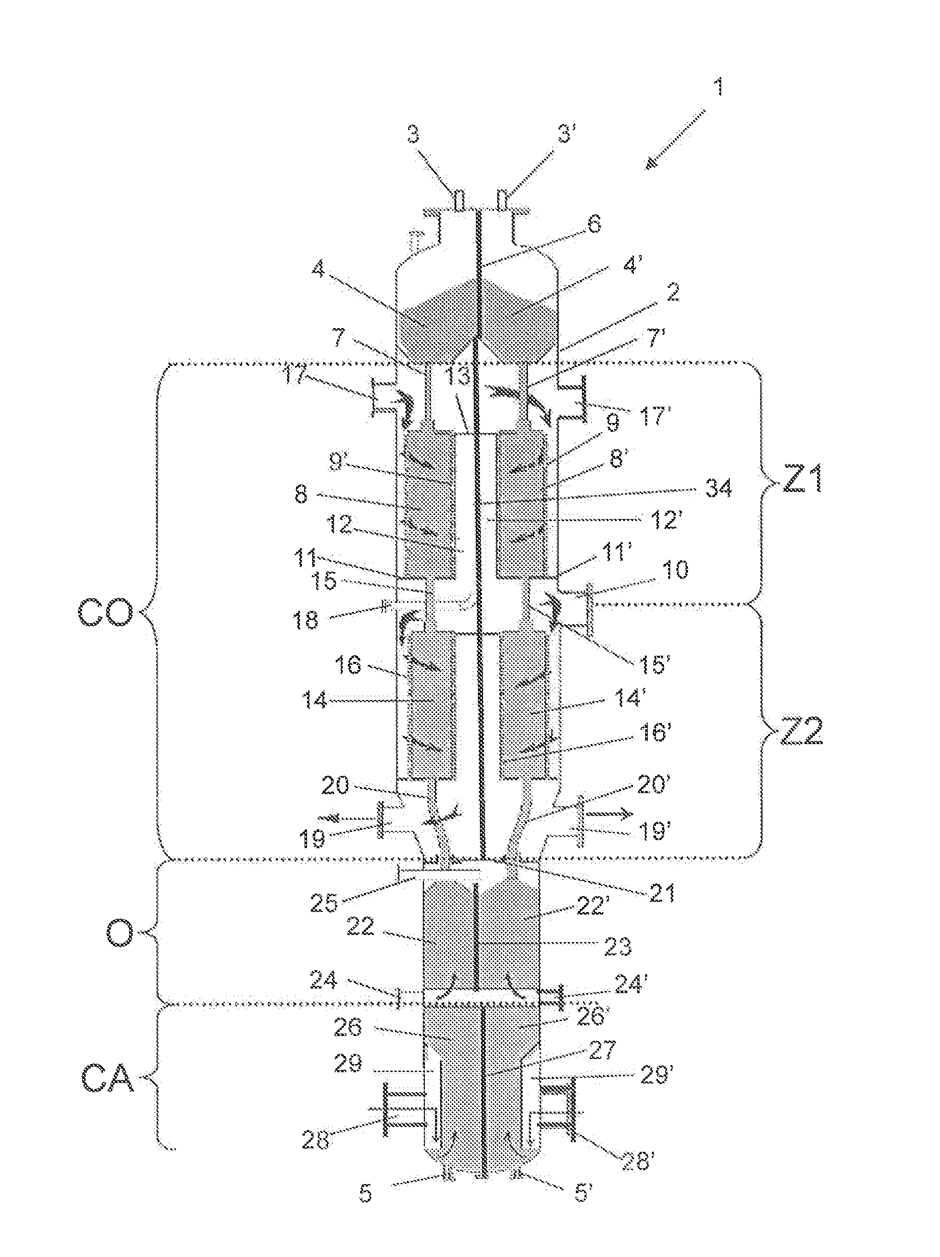
[0049]FIG. 1 represents a sectional view in a vertical plane of a catalyst regenerator in accordance with the invention;

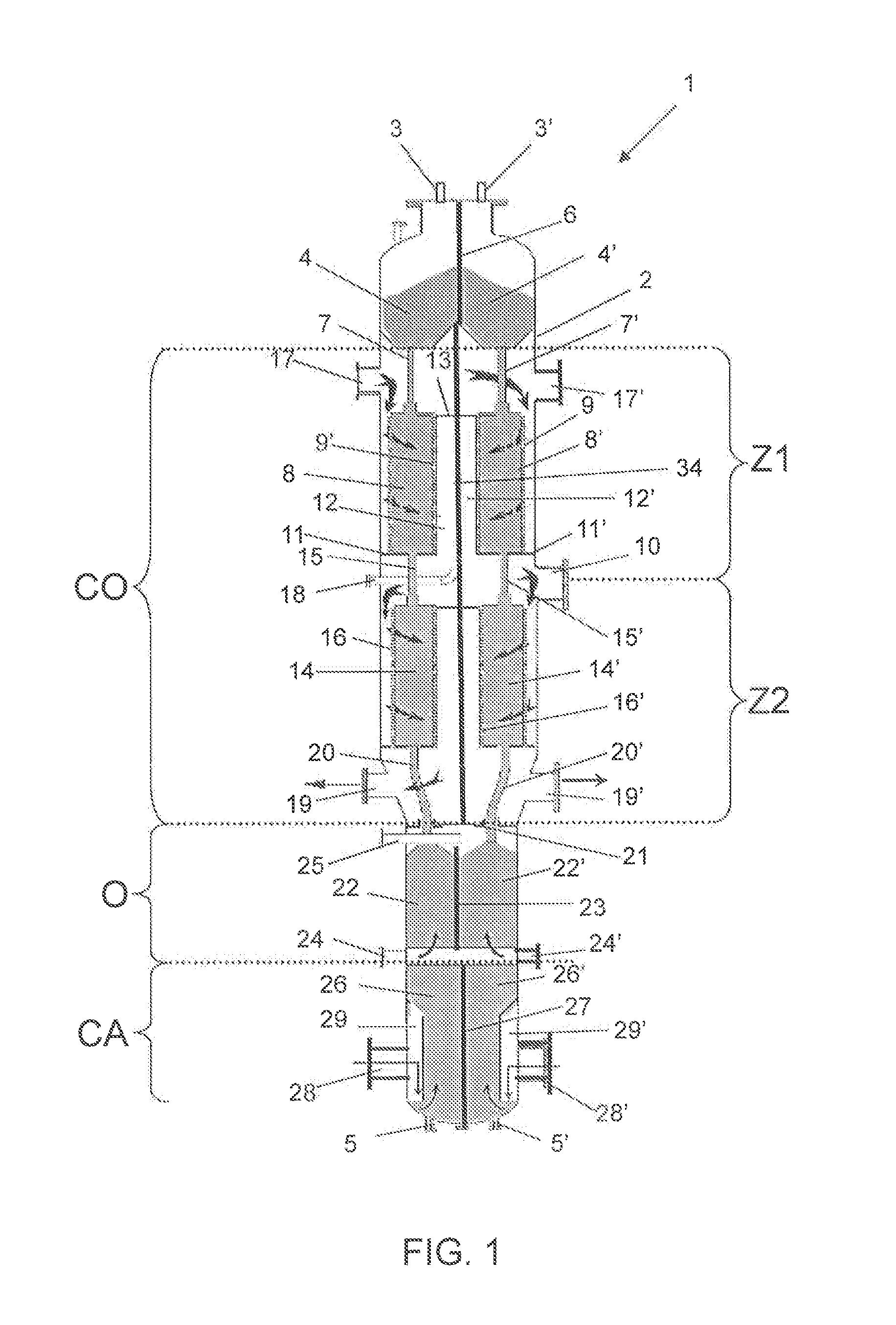
[0050]FIG. 2 is a sectional view in a plane perpendicular to the vertical axis of the regenerator of FIG. 1 in the combustion zone;

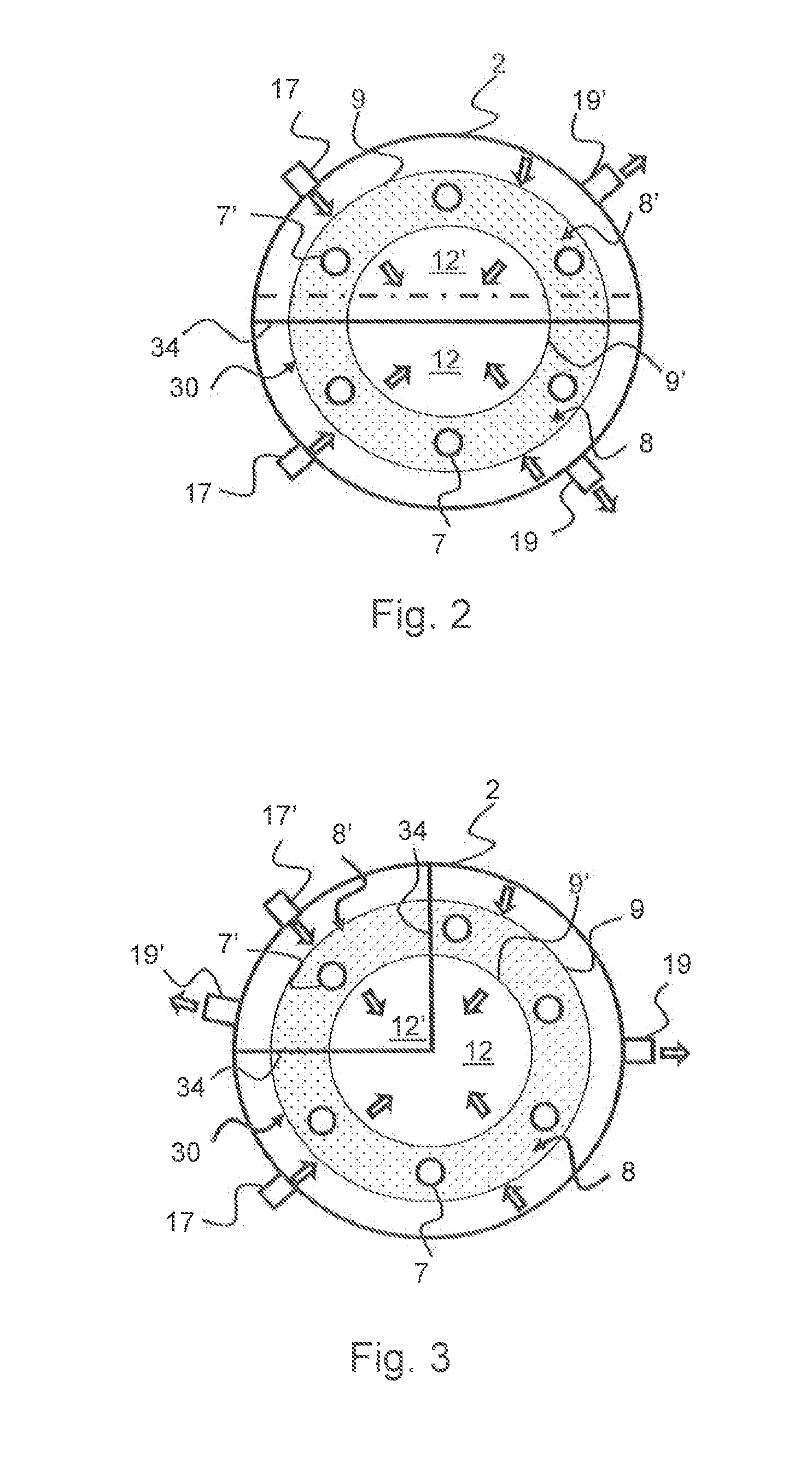
[0051]FIG. 3 is a sectional view in a plane perpendicular to the vertical axis of a regenerator in accordance with another embodiment of the combustion zone;

[0052]FIG. 4 is a sectional view in a plane perpendicular to the vertical axis of a regenerator in the combustion zone in accordance with an alternative embodiment;

[0053]FIG. 5 is a perspective view of the oxychlorination and calcining zones of a regenerator in accordance with the invention;

[0054]FIG. 6 is a simplified flowsheet for the process of the invention.

[0055]In FIG. 1, the catalyst regeneration reactor (or regenerator)...


PUM

PropertyMeasurementUnit
diameteraaaaaaaaaa
temperatureaaaaaaaaaa

Abstract

The present invention concerns a moving bed catalyst regenerator (1) comprising a vessel (2) extending in a vertical direction, said vessel being divided into at least two regeneration zones extending along the vertical height of said vessel, in which particles of catalyst move under gravity, in which each regeneration zone comprises, in succession and in the order in which the catalysts move:a) a combustion section (CO);b) an oxychlorination section (O) disposed below the combustion section and comprising means for bringing catalyst from the combustion section (CO) to the oxychlorination section (O);c) a calcining section (CA) disposed below the oxychlorination section;characterized in that the regeneration zones are separated from each other by a separation means which is impermeable to catalysts and to gases in a manner such that the catalysts of each of the zones are capable of being regenerated under different operating conditions.

Description

[0001]The present invention relates to the field of the conversion of hydrocarbons, and more particularly to that of catalytic reforming. The invention pertains to a regeneration reactor (or regenerator) for catalysts, to a catalytic reforming unit using a regenerator in accordance with the invention and also to a catalytic reforming process.PRIOR ART[0002]The reformation (or catalytic reforming) of naphtha type hydrocarbon cuts is well known in the refining field. Starting from these hydrocarbon cuts, this reaction can be used to produce bases for high octane number fuel and / or aromatic cuts for petrochemicals, while at the same time supplying the refinery with the hydrogen necessary for other operations.[0003]The catalytic reforming process consists of bringing the hydrocarbon cut containing paraffinic compounds and naphthenes into contact with hydrogen and a reforming catalyst, for example platinum-containing catalyst, and of converting the paraffinic compounds and naphthenes int...

Claims


Application Information

Patent Timeline
Patent Type & Authority Applications(United States)
IPC IPC(8): C10G59/02B01J8/00B01J8/08B01J38/44B01J38/16
CPCC10G59/02B01J38/44B01J38/16B01J8/08B01J8/0015B01J2208/00823B01J2208/00752B01J8/008B01J8/125B01J19/1862B01J38/32B01J38/34C10G47/32C10G49/007C10G49/18B01J38/22C10G35/10B01J8/085C10G2300/70B01J8/26B01J38/00
Inventor BAZER-BACHI, FREDERICLEMAIRE, ERICLAMBERT, FABIAN
Owner INST FR DU PETROLE
Why Eureka
Try Eureka