Physical quantity sensor element, physical quantity sensor, electronic equipment, and movable body

a technology of physical quantity and sensor element, which is applied in the direction of acceleration measurement using interia force, instruments, devices using electric/magnetic means, etc., can solve the problems of detection accuracy deterioration and detection accuracy degradation, and achieve excellent detection accuracy

Inactive Publication Date: 2016-03-10
COLUMBIA PEAK VENTURES LLC
View PDF2 Cites 1 Cited by
  • Summary
  • Abstract
  • Description
  • Claims
  • Application Information

AI Technical Summary

Benefits of technology

[0007]An advantage of some aspects of the invention is to provide a physical quantity sensor element having excellent detection accuracy, or a physical quantity sensor which is provided with the physical quantity sensor element, electronic equipment, and a movable body.
[0010]According to the physical quantity sensor element as described above, in the first direction which is a direction of the driving vibration of the driving portion, the first beam portion is likely to be more bent than the second beam portion, and thus it is possible to reduce the transfer of vibration from the driving vibration of the driving portion to the detecting portion and to efficiently excite the driving vibration on the driving portion. In addition, even though the cross-sectional shape of the first beam portion is formed into, for example, a parallelogram shape or a trapezoid shape other than the rectangular shape, the direction in which the unnecessary vibration occurs in the driving portion corresponds to a direction along a third axis orthogonal to the second axis in the reference surface. Thus, although the unnecessary vibration is transferred to the detecting portion from the driving portion, it is possible to reduce the occurrence of detection errors with negligible effect on the detection vibration of the detecting portion. In addition, in the second direction which corresponds to the direction of the detecting vibration of the detecting portion, the second beam portion is likely to be bent, and thus it is possible to efficiently excite detecting vibration on the detecting portion to vibrate. As described, the physical quantity sensor element of the invention has excellent detection accuracy.Application Example 2
[0028]As such, it is possible to provide the movable body which includes the physical quantity sensor element having excellent detection accuracy.

Problems solved by technology

However, in the angular velocity sensor according to JP-A-2000-337884, the second vibrating body for detecting vibration is supported by the first vibrating body for driving vibration via the second supporting beam, and thus when unnecessary vibration is generated in a direction different from a desired driving vibration, the unnecessary vibration is transferred to the second vibrating body from the first vibrating body via the second supporting beam, thereby causing deterioration of detection accuracy.
For example, a cross-sectional shape of the first supporting beam is supposed to be, for example, a rectangular shape which is an ideal shape; however, the cross-sectional shape may become a parallelogram shape or a trapezoid shape without being the ideal shape due to a processing error in some cases.
At this time, this unnecessary vibration is transferred to the second vibrating body as well, and thus leakage vibration occurs, thereby causing the detection accuracy to be deteriorated.

Method used


Image

  • Physical quantity sensor element, physical quantity sensor, electronic equipment, and movable body
  • Physical quantity sensor element, physical quantity sensor, electronic equipment, and movable body
  • Physical quantity sensor element, physical quantity sensor, electronic equipment, and movable body

Examples


first embodiment

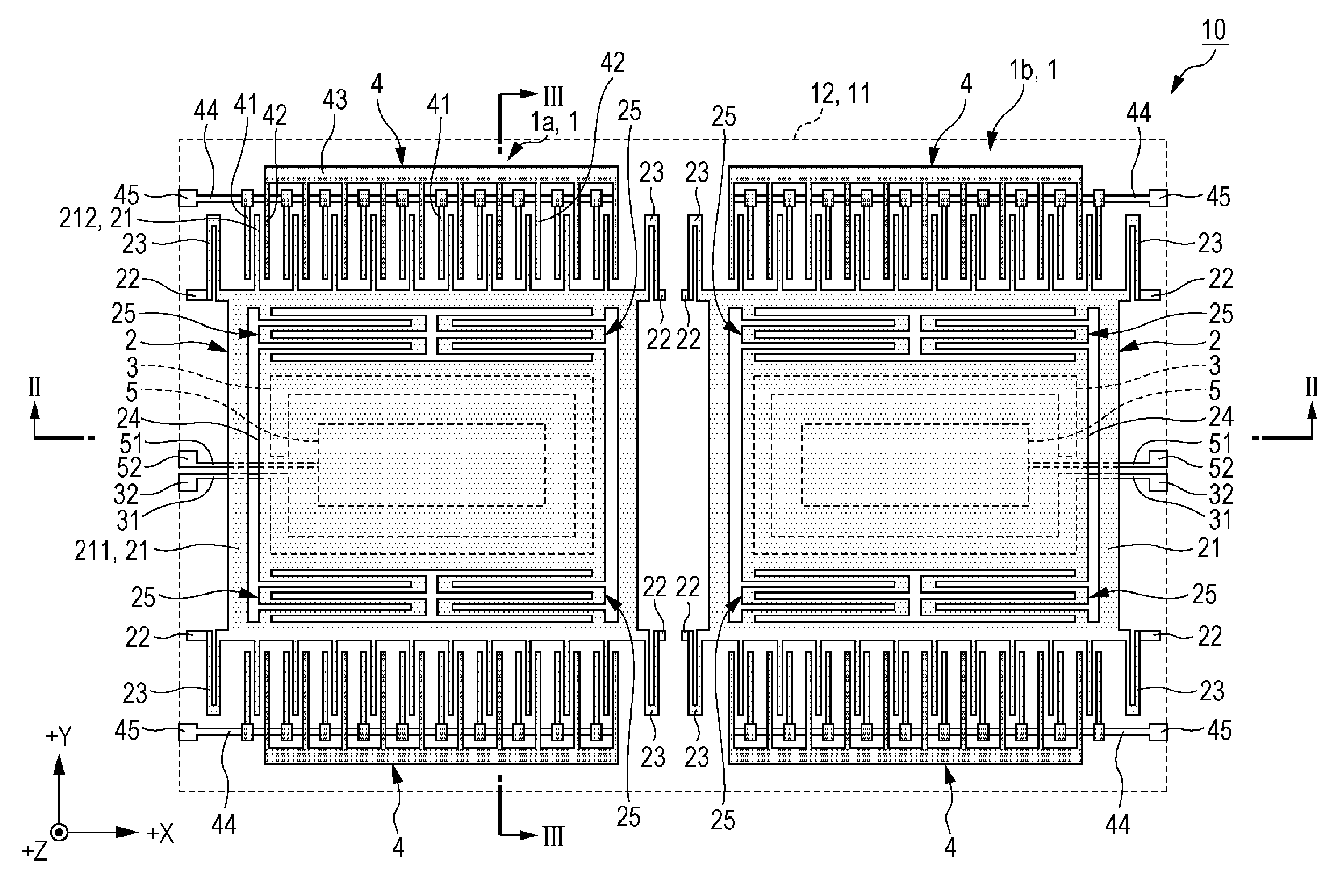
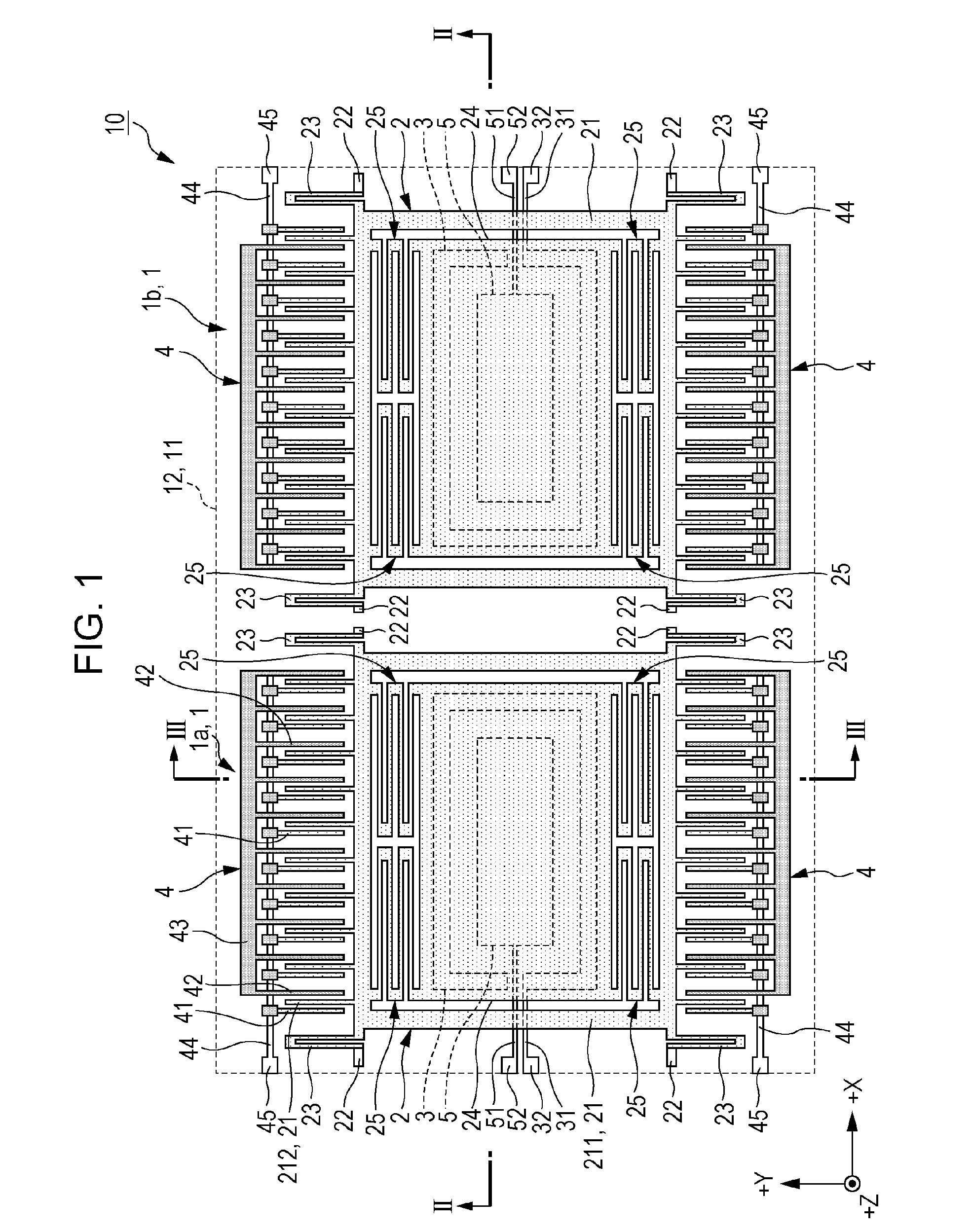
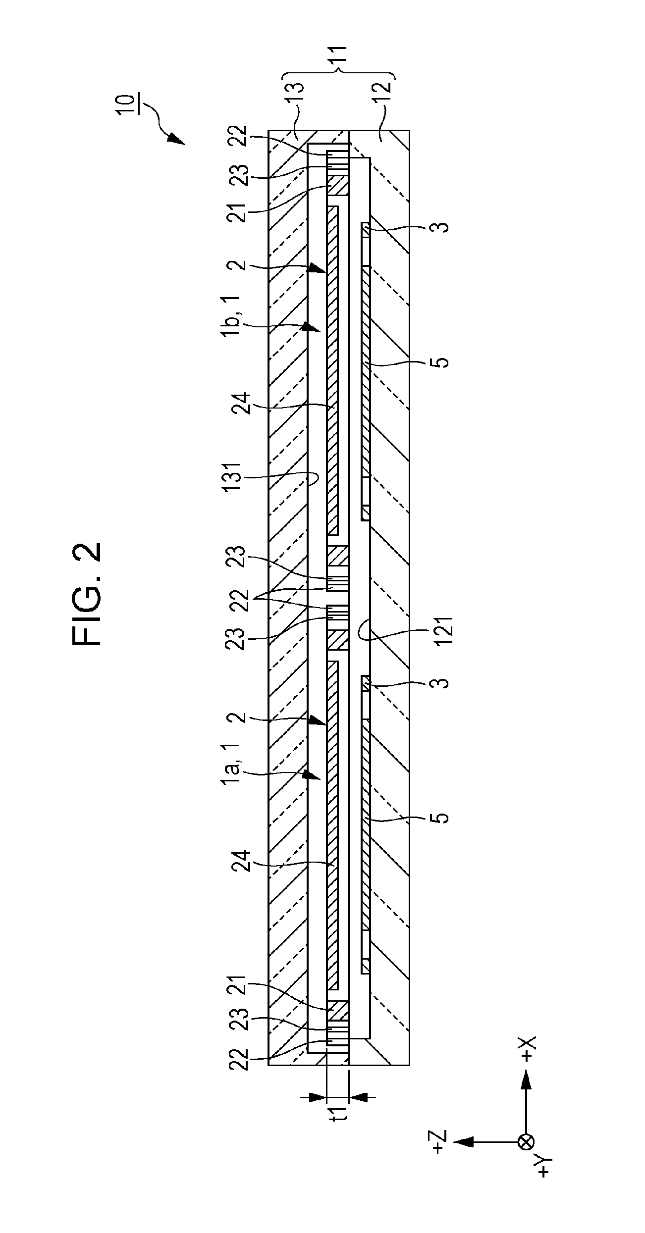
[0043]FIG. 1 is a plan view illustrating the physical quantity sensor according to the first embodiment of the invention, FIG. 2 is a sectional view taken along line IIA-IIA in FIG. 1, and FIG. 3 is a sectional view taken along line IIB-IIB in FIG. 1. In addition, FIG. 4A and FIG. 4B are schematic diagrams for illustrating an operation of the physical quantity sensor (a state to which an angular velocity is not added) illustrated in FIG. 1, and FIG. 4A is a plan view and FIG. 4B is a sectional view. FIG. 5A and FIG. 5B is a schematic diagram for illustrating an operation of the physical quantity sensor (a state to which an angular velocity is added) illustrated in FIG. 1, and FIG. 5A is a plan view and FIG. 5B is a sectional view.

[0044]Meanwhile, in the drawings, for convenience of explanation, three axes of an X-axis (a third axis), a Y-axis (a second axis), and a Z-axis (a first axis) which are orthogonal to each other are indicated by arrows, and a tip end side of the arrow is se...

second embodiment

[0101]Next, the second embodiment of the invention will be described.

[0102]FIG. 6 is a plan view illustrating the physical quantity sensor according to the second embodiment of the invention. In addition, FIG. 7 is a schematic diagram for illustrating an operation of the physical quantity sensor (a state to which an angular velocity is not added) illustrated in FIG. 6, and FIG. 7A is a plan view and FIG. 7B is a sectional view.

[0103]The description of the second embodiment is the same as that of the first embodiment described above except that the physical quantity sensor element is provided with a coupling structure for connecting two vibration structures to each other.

[0104]Note that, in the following description, regarding the second embodiment, the description will focus on the differences from the embodiment described above and the same matters will be omitted.

[0105]The physical quantity sensor element 1A as illustrated in FIG. 6 is provided with two vibration structures 2a and...


PUM


Abstract

A physical quantity sensor element is formed into a plane-shape which extends along an XY plane, and is provided with a driving portion which vibrates in a Z-axis direction, a detecting portion which vibrates in an X-axis direction due to Coriolis effect acting on the driving portion, a beam portion which connects the driving portion and the detecting portion, a fixing portion, and a beam portion which connects the detecting portion and the fixing portion, in which a spring constant of the beam portion in the Z-axis direction is smaller than a spring constant of the beam portion in the Z-axis direction, and a spring constant of the beam portion in the Z-axis direction is greater than a spring constant of the beam portion in the X-axis direction.

Description

BACKGROUND[0001]1. Technical Field[0002]The present invention relates to a physical quantity sensor element, a physical quantity sensor, electronic equipment, and a movable body.[0003]2. Related Art[0004]Recently, as a physical quantity sensor element using a silicon micro electro mechanical system (MEMS) technology, for example, a capacitance type gyro sensor element (an angular velocity sensor) for detecting angular velocity has been known (for example, refer to JP-A-2000-337884).[0005]For example, an angular velocity sensor according to JP-A-2000-337884 is provided with a support fixing portion, a first vibrating body (a driving portion) which is supported with respect to the support fixing portion via a first supporting beam, and a second vibrating body (a detecting portion) which is supported with respect to the first vibrating body via a second supporting beam. In the angular velocity sensor, a load vibrating body including the first vibrating body and the second vibrating bod...

Claims


Application Information

Patent Timeline
Patent Type & Authority Applications(United States)
IPC IPC(8): G01C19/5705
CPCG01C19/5705G01C19/574
Inventor FURUHATA, MAKOTO
Owner COLUMBIA PEAK VENTURES LLC
Why Eureka
Try Eureka