Improved ankle replacement apparatus and method

Active Publication Date: 2016-03-17
NORTH DAKOTA STATE UNIV RES FOUND
View PDF8 Cites 5 Cited by
  • Summary
  • Abstract
  • Description
  • Claims
  • Application Information

AI Technical Summary

Benefits of technology

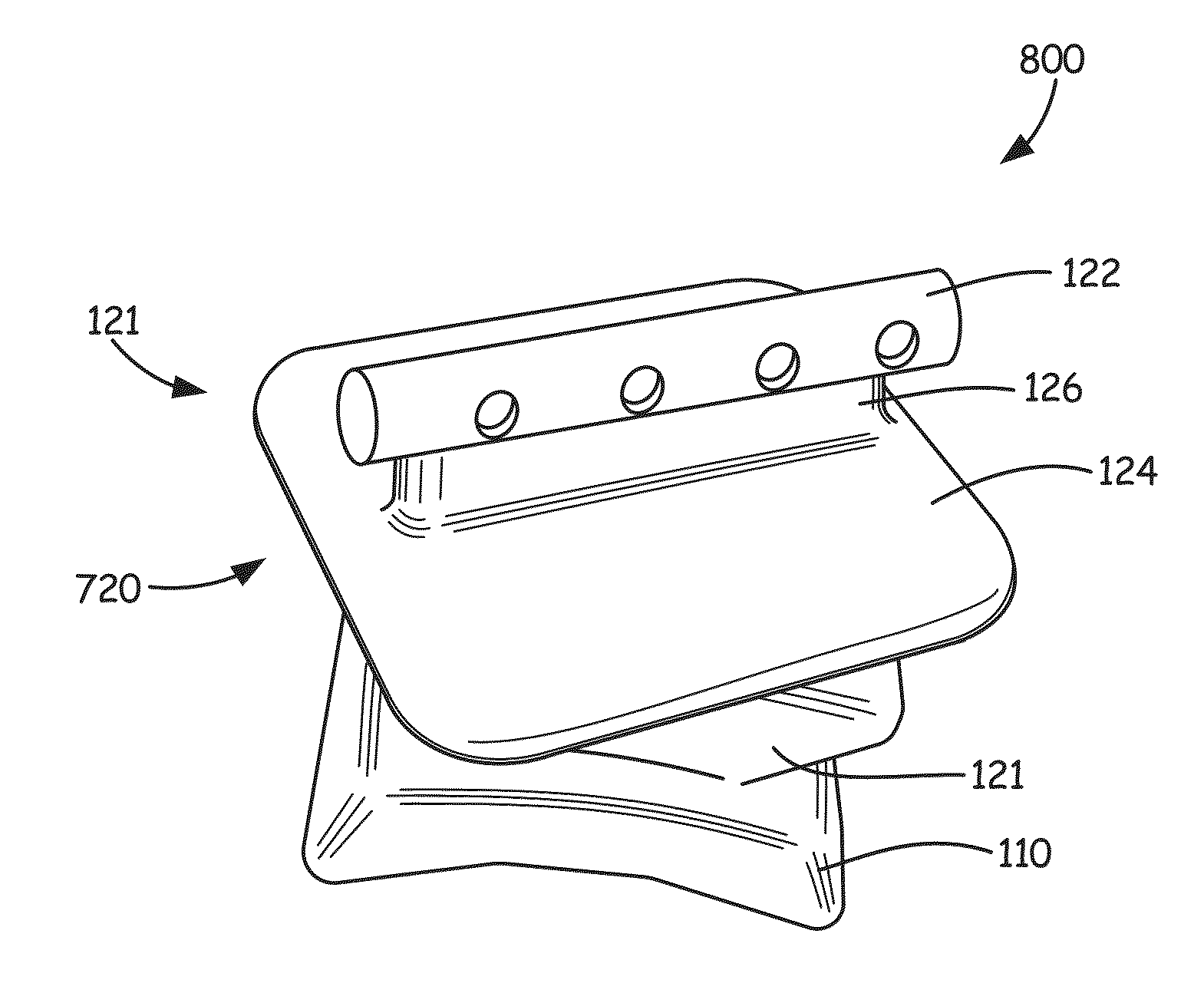
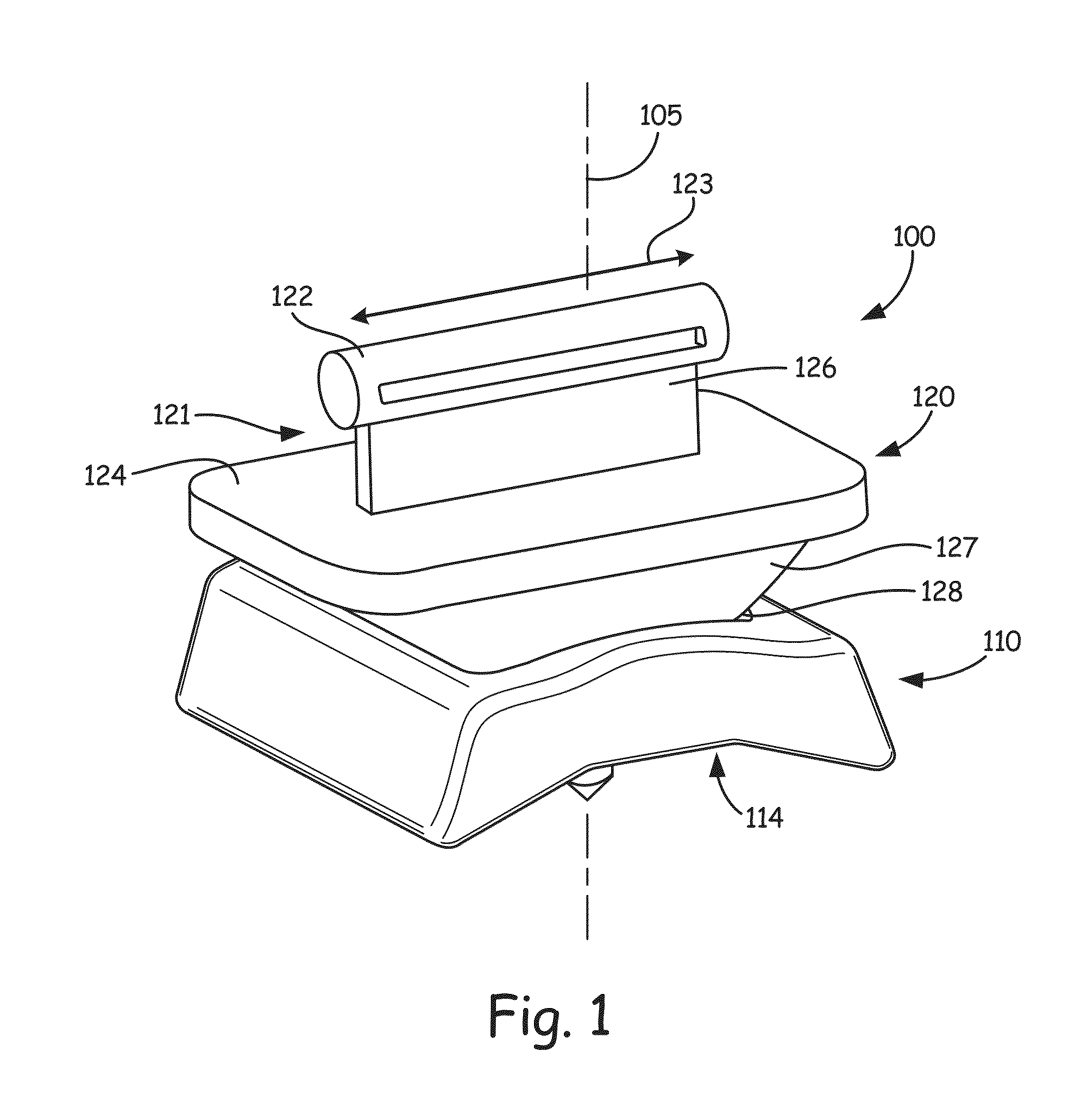
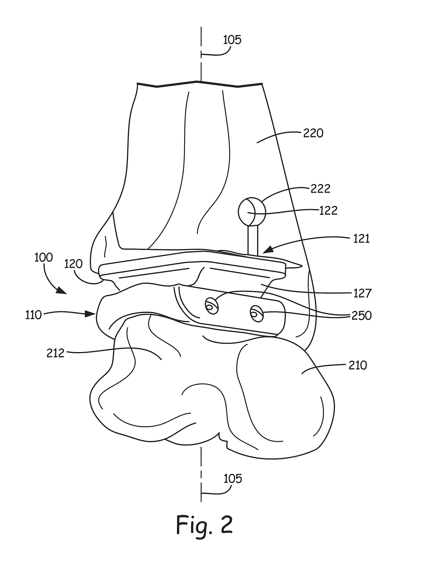
[0017]In some exemplary embodiments, the tibial component 120; 720 comprises a tibial bearing component 127 providing the convex bearing surface 128 and a tibial attachment component 121 configured to be attached to the patient's tibia. In some exemplary embodiments, the tibial bearing component and the tibial attachment component are configured to be secured to one another. These components can be secured to one another by a pivotal attachment to allow rotation between the tibial bearing component and the tibial attachment component, allowing for the benefits of a mobile bearing implant while keeping the bearing fixed. The rotation can be about an axis of loading of the ankle replacement prosthesis.
[0018]In some exemplary embodiments, the talar component further comprises a plurality of screw receiving apertures 250 each disposed and arranged on the talar component to receive a corresponding one of a plurality of sc

Problems solved by technology

As in the need for hip and knee replacements, patients requiring an ankle replacement no longer have a fully functional ankle.
For many years, arthrodesis, or ankle fusion, was the primary technique for reducing the pain in patients; however, fusing the ankle bones together greatly reduces the joint's range of motion, and could potentially cause serious alterations in gait, which often leads to additional joint and mobility complications.
Throughout th

Method used


Image

  • Improved ankle replacement apparatus and method
  • Improved ankle replacement apparatus and method
  • Improved ankle replacement apparatus and method

Examples


Example

[0032]Before any embodiments of the invention are explained in detail, it is to be understood that the invention is not limited in its application to the details of construction and the arrangement of components set forth in the following description or illustrated in the following drawings. The invention is capable of other embodiments and of being practiced or of being carried out in various ways. Also, it is to be understood that the phraseology and terminology used herein is for the purpose of description and should not be regarded as limiting. The use of “including,”“comprising,” or “having” and variations thereof herein is meant to encompass the items listed thereafter and equivalents thereof as well as additional items. Unless specified or limited otherwise, the terms “connected,”“coupled” and variations thereof are used broadly and encompass both direct and indirect connections and couplings. Further, “connected” and “coupled” are not restricted to physical or mechanical con...


PUM


Abstract

In some exemplary embodiments, an ankle replacement prosthesis includes a tibial component which provides a convex bearing surface, and a talar component which provides a concave bearing surface configured to interface with the convex bearing surface of the tibial component to provide a joint of the ankle replacement prosthesis. The tibial component is configured to be attached to a patient's tibia and the talar component is configured to be attached to the patient's talus.

Description

CROSS-REFERENCE TO RELATED APPLICATION[0001]This application is a Section 371 National Stage Application of International Application No. PCT / US2014 / 036399, filed May 1, 2014 and published, in English, as WO 2014 / 179589 A1 on Nov. 6, 2014.FIELD OF THE INVENTION[0002]The present invention relates to ankle replacement prosthesis and methods of implanting the same.BACKGROUND OF THE INVENTION[0003]As in the need for hip and knee replacements, patients requiring an ankle replacement no longer have a fully functional ankle. The most common end-stage ankle complications arise from arthritic pain either from old age or previous trauma. For many years, arthrodesis, or ankle fusion, was the primary technique for reducing the pain in patients; however, fusing the ankle bones together greatly reduces the joint's range of motion, and could potentially cause serious alterations in gait, which often leads to additional joint and mobility complications. To many people, having a fully functional ank...

Claims


Application Information

Patent Timeline
IPC IPC(8): A61F2/42A61F2/30A61L27/16A61L27/44
CPCA61F2/4202A61F2/30767A61L27/443A61F2002/4207A61F2002/3093A61F2002/4205A61L27/16A61F2002/30784A61F2002/30878A61F2002/30364A61F2002/30426A61F2002/30883A61F2002/30884A61F2002/30902A61F2/42
Inventor AELONY, JARED S.AZARMI, FARDADULVEN, CHAD A.
Owner NORTH DAKOTA STATE UNIV RES FOUND
Why Eureka
Try Eureka