
A light emitting diode module

a diode module and light-emitting technology, applied in the field of light-emitting diodes, can solve the problems of low thermal conductivity, unsuitable for heat conduction and efficient heat removal, and low thermal conductivity

Active Publication Date: 2016-03-17
SIGNIFY HLDG BV
View PDF1 Cites 6 Cited by
  • Summary
  • Abstract
  • Description
  • Claims
  • Application Information

AI Technical Summary

Benefits of technology

The present invention aims to improve LED modules by integrating a heat conduction part that increases heat removal efficiency without the need for a larger heat sink. The LED modules may also comprise heat conducting fastening means to further enhance heat conduction between the light source device and the heat sink. The technical effects include increased heat removal efficiency and smaller LED modules that meet standard specifications.

Problems solved by technology

A cover according to the prior art is normally made of a material with a relatively low thermal conductivity which is as such not suitable to be used for heat conduction and efficient heat removal.

Method used


Image

  • A light emitting diode module
  • A light emitting diode module
  • A light emitting diode module

Examples


Embodiment Construction

[0028]The present invention will now be described more fully hereinafter with reference to the accompanying drawings, in which currently preferred embodiments of the invention are shown. This invention may, however, be embodied in many different forms and should not be construed as limited to the embodiments set forth herein. Rather, these embodiments are provided for thoroughness and completeness, and fully convey the scope of the invention to the skilled person.

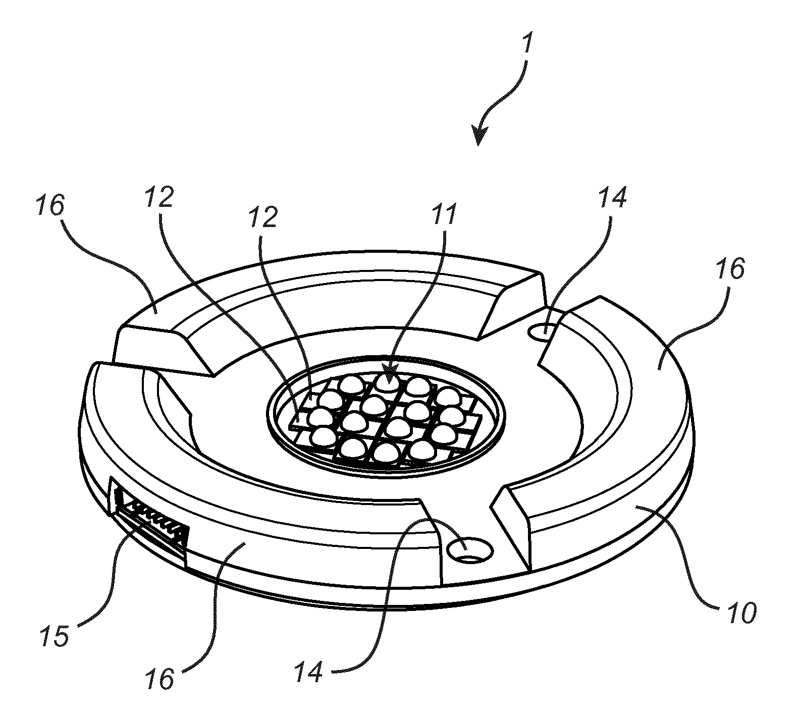
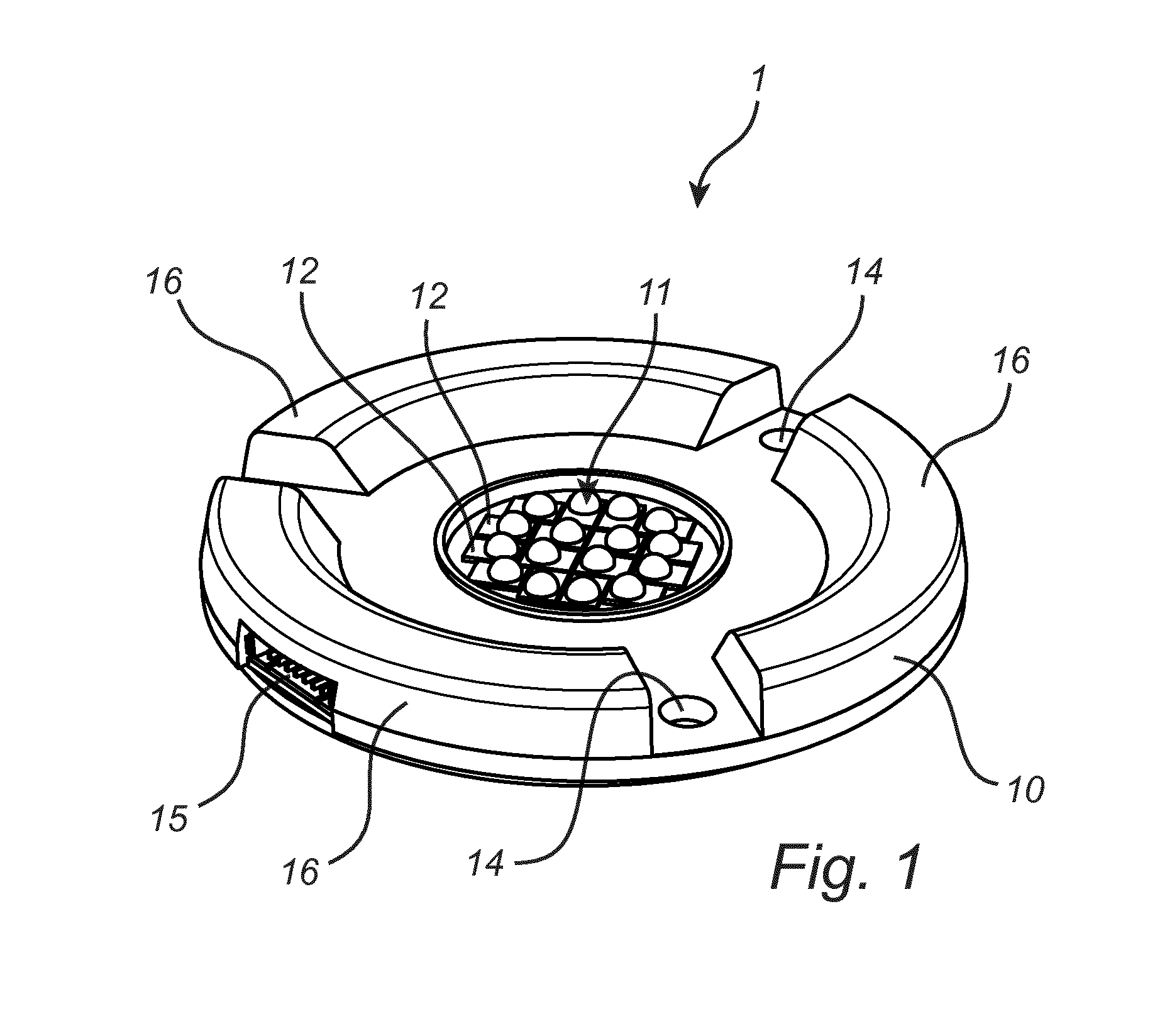
[0029]A basic design of a light emitting diode (LED) module 1, in the form of a spot module, is illustrated in FIG. 1. The LED module 1 comprises a cover 10 and a light source device 11. The light source device 11 comprises in this embodiment a plurality of LED packages 12. The LED packages 12 may be may be arranged on a printed circuit board (PCB).

[0030]A conventional cover of this type is typically made of a material which has a relatively low thermal conductivity and which is therefore not suitable to efficiently conduct...


PUM


Abstract

The present application relates to a light emitting diode module comprising: a light source device (11), a cover (10) for said light source device (11), the cover (10) being arranged to connect to an optical device (21); wherein said cover (10) comprises a heat conducting part (24, 34) which has an at least one order of magnitude higher thermal conductivity than the remaining part of the cover (10) and which is arranged to thermally connect said light source device (11) with said optical device (21). The present application further relates to a corresponding cover for a light source device (11) in a light emitting diode module (1).

Description

FIELD OF THE INVENTION[0001]The present invention relates to a lighting device, and in particular to an improved light emitting diode module.BACKGROUND OF THE INVENTION[0002]Light emitting diode (LED) modules, such as in the form of a spot module, is one of many lighting device types which are available today. LED modules typically comprises a light source device, such as one or more LED packages, a chip on board (COB) module or a printed circuit board (PCB) with discrete LED packages, and a cover for the light source device. The cover is provided for e.g. protecting the light source device, providing a mechanical reference surface, and / or connection of a reflector thereto.[0003]The light source device may further comprise a phosphor element, in some cases remotely arranged, for modifying the light provided by the LEDs. For example, white light may be achieved by LEDs providing blue light which passes through a phosphor element, where some of the light is converted into yellow light...

Claims


Application Information

Patent Timeline
Patent Type & Authority Applications(United States)
IPC IPC(8): F21V29/73F21K99/00F21V29/502F21V29/505F21V29/71
CPCF21V29/73F21K9/56F21Y2101/02F21V29/713F21V29/502F21K9/00F21V17/12F21V29/505F21K9/64F21Y2115/10
Inventor CREUSEN, MARTINUS PETRUSDE GRAAF, JAN
Owner SIGNIFY HLDG BV
Learn More