Electronic apparatus and wireless power transmission system

a technology of wireless transmission and electric equipment, applied in the direction of exchanging data chargers, inductances, transportation and packaging, etc., can solve the problems of power transmission efficiency reduction and loss in conversion, and achieve the effect of not reducing transmission efficiency

Active Publication Date: 2016-03-17
MURATA MFG CO LTD
View PDF19 Cites 19 Cited by
  • Summary
  • Abstract
  • Description
  • Claims
  • Application Information

AI Technical Summary

Benefits of technology

[0008]Accordingly, in order to resolve the above problems, the present system and method described herein provide an electronic apparatus capable of transmitting power that is received to another apparatus without reducing the transmission efficiency and a wireless power transmission system including the electronic apparatus.

Problems solved by technology

However, for the power receiving apparatus described in Patent Document 1, it is necessary to convert the alternating-current voltage that is received into the direct-current voltage and convert the direct-current voltage into the alternating-current voltage again, there are problems in that loss occurs in the conversion and power transmission efficiency is reduced.

Method used


Image

  • Electronic apparatus and wireless power transmission system
  • Electronic apparatus and wireless power transmission system
  • Electronic apparatus and wireless power transmission system

Examples


first embodiment

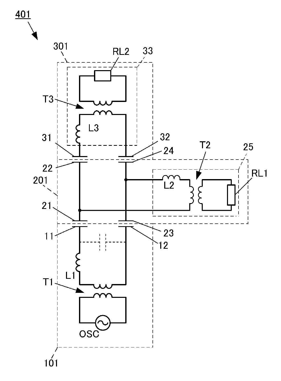
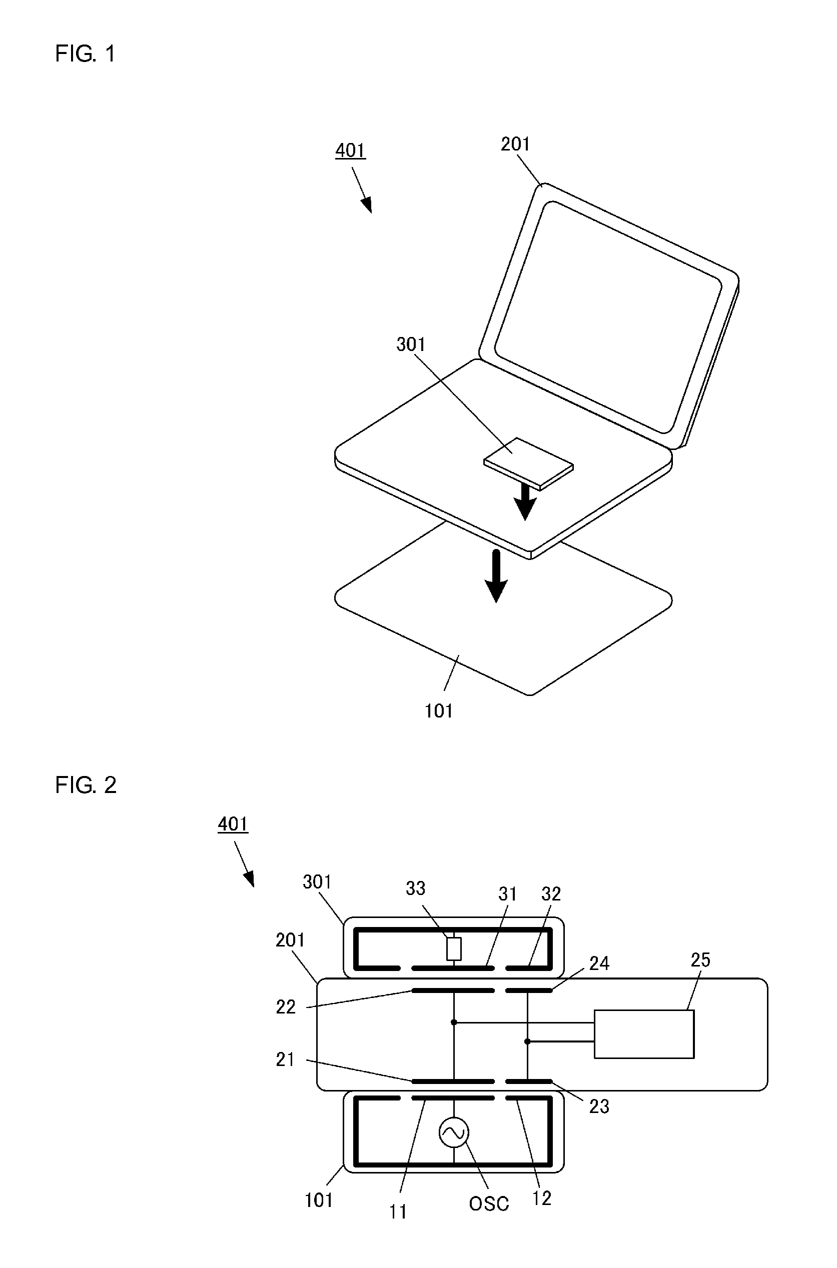
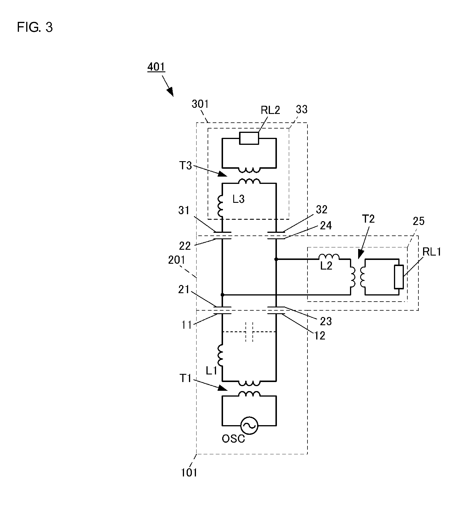
[0038]FIG. 1 illustrates a wireless power transmission system according to a first embodiment.

[0039]A wireless power transmission system 401 according to the present embodiment includes a power transmitting apparatus 101 and two power receiving apparatuses 201 and 301. The power transmitting apparatus 101 is embedded in, for example, a desk in a state in which part of the power transmitting apparatus 101 is exposed. Upon placement of the power receiving apparatus 201 on the exposed surface of the power transmitting apparatus 101, power is wirelessly transmitted from the power transmitting apparatus 101 to the power receiving apparatus 201. The power receiving apparatus 201 is, for example, a notebook personal computer (PC) or a tablet terminal. The power receiving apparatus 201 corresponds to an electronic apparatus and a first power receiving apparatus of the present invention.

[0040]Upon placement of the power receiving apparatus 301 on the power receiving apparatus 201, the power ...

second embodiment

[0062]FIG. 6 is a circuit diagram of a wireless power transmission system 402 according to a second embodiment. The wireless power transmission system 402 according to the present embodiment includes the power transmitting apparatus 101, a relay power receiving apparatus 202, and the power receiving apparatus 301. Since the power transmitting apparatus 101 and the power receiving apparatus 301 are the same as those in the first embodiment, a description of the power transmitting apparatus 101 and the power receiving apparatus 301 is omitted herein.

[0063]The relay power receiving apparatus 202 includes a transformer T4. A primary winding of the transformer T4 is connected to the active electrode 21 and the passive electrode 23 and a secondary winding of the transformer T4 is connected to the active electrode 22 and the passive electrode 24. The alternating-current voltage induced at the active electrode 21 and the passive electrode 23 is applied to the active electrode 22 and the pas...

third embodiment

[0066]FIG. 7 is a circuit diagram of a wireless power transmission system 403 according to a third embodiment. The wireless power transmission system 403 according to the present embodiment includes the power transmitting apparatus 101, a relay power receiving apparatus 203, and the power receiving apparatus 301. The power transmitted from the power transmitting apparatus 101 is simultaneously transmitted to both the power transmitting apparatus 101 and the power receiving apparatus 301 in the first embodiment. The third embodiment differs from the first embodiment in that the power transmitted from the power transmitting apparatus 101 is alternately transmitted to the relay power receiving apparatus 203 and the power receiving apparatus 301. The difference is described here. Since the power transmitting apparatus 101 and the power receiving apparatus 301 are the same as those in the first embodiment, a description of the power transmitting apparatus 101 and the power receiving appa...


PUM


Abstract

A wireless power transmission system transmits power from a power transmitting apparatus to a relay power receiving apparatus by applying voltage to an active electrode in the power transmitting apparatus, which is opposed to an active electrode in the relay power receiving apparatus, and a passive electrode in the power transmitting apparatus, which is opposed to a passive electrode in the relay power receiving apparatus.

Description

CROSS-REFERENCE TO RELATED APPLICATIONS[0001]The present application is a continuation of PCT / JP2014 / 064063 filed May 28, 2014, which claims priority to Japanese Patent Application No. 2013-118461, filed Jun. 5, 2013, the entire contents of each of which are incorporated herein by reference.FIELD OF THE INVENTION[0002]The present invention relates to an electronic apparatus to which power is wirelessly transmitted from an external apparatus and a wireless power transmission system.BACKGROUND OF THE INVENTION[0003]Systems using magnetic-field coupling or electric-field coupling have hitherto been proposed as systems that wirelessly transmit power to portable electronic devices. In the magnetic-field coupling systems, power is transmitted from a primary coil in a power transmitting apparatus to a secondary coil in a power receiving apparatus using the magnetic field. In the electric-field coupling systems, upon proximity (placement) of the power receiving apparatus to (in) the power t...

Claims


Application Information

Patent Timeline
Patent Type & Authority Applications(United States)
IPC IPC(8): H02J5/00H02J7/02H02J7/04
CPCH02J5/005H02J7/04H02J7/025H02J50/05H02J2207/20H02J50/80H02J50/40H02J50/502H02J7/00034H02J50/12H02J7/00
Inventor SHINODA, SATOSHI
Owner MURATA MFG CO LTD
Why Eureka
Try Eureka