Light Delivery Systems and Related Methods of Use

a technology of light delivery and assembly, applied in the field of light delivery assemblies/systems, can solve the problems of difficult to see the surgical site and video monitors, intrinsically heavy, and difficult to provide good/sufficient light to a site/target (e.g., surgical site)

Active Publication Date: 2016-03-24
SPECTRUM MEDICAL TECH LLC
View PDF8 Cites 20 Cited by
  • Summary
  • Abstract
  • Description
  • Claims
  • Application Information

AI Technical Summary

Benefits of technology

[0008]The present disclosure provides advantageous light delivery assemblies / systems, and improved methods for using the same. More particularly, the present disclosure provides improved light delivery assemblies / systems that provide light to and / or illuminate / treat predetermined locations (e.g., surgical sites / targets).

Problems solved by technology

In general, providing good / sufficient light to a site / target (e.g., surgical site) can be problematic.
Not only can overhead lights be unwieldy, they can be both a source of glare and of shadows simultaneously, making it difficult to see the surgical site and the video monitors.
Head lamps also cast shadows, for example, of a surgeon's hands or instruments, and are intrinsically heavy (or require cumbersome connections to external light or power sources).
Small lamps and other light-emitting structures can be unnecessarily costly and complicated.
They typically require bulbs or fiber-optical elements, as well as a source of power which potentially becomes an electric shock risk to the patient.
Not only do they have multiple connections and bulky fixtures that complicate surgery, they can be problematic sources of heat.
Also, a light fixture that incorporates elements such as light bulbs into a complex structure requires significant manufacturing costs.
Moreover, light sources (whether overhead or localized) can cause glares and reflections that are blinding or distracting.
For example, light that glares off of monitors interferes with the ability of medical staff to monitor a patient's vital signs, and light reflecting from steel or mirrored surfaces and instruments can interfere with a surgeon's focus.

Method used


Image

  • Light Delivery Systems and Related Methods of Use
  • Light Delivery Systems and Related Methods of Use
  • Light Delivery Systems and Related Methods of Use

Examples


Embodiment Construction

[0056]The exemplary embodiments disclosed herein are illustrative of advantageous light delivery assemblies, and systems of the present disclosure and methods / techniques thereof. It should be understood, however, that the disclosed embodiments are merely exemplary of the present disclosure, which may be embodied in various forms. Therefore, details disclosed herein with reference to exemplary light delivery assemblies / fabrication methods and associated processes / techniques of assembly and use are not to be interpreted as limiting, but merely as the basis for teaching one skilled in the art how to make and use the advantageous light delivery assemblies / systems and / or alternative assemblies of the present disclosure.

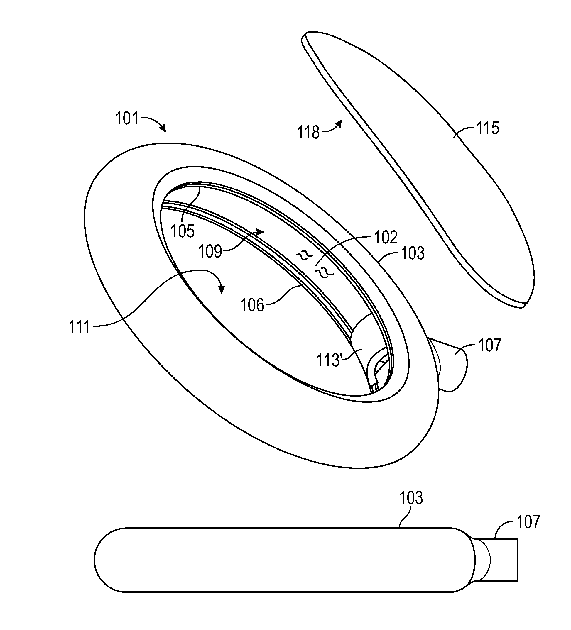
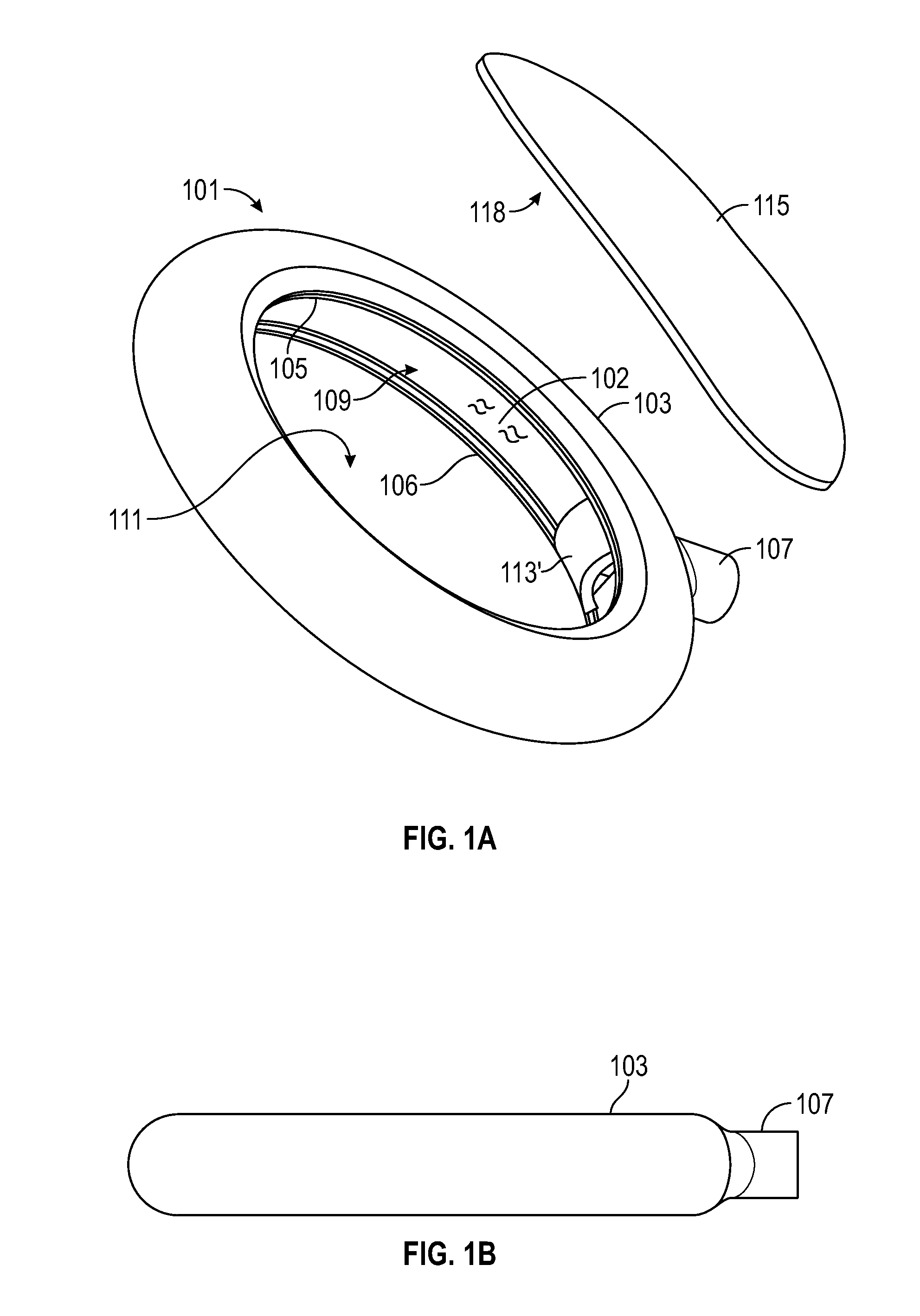
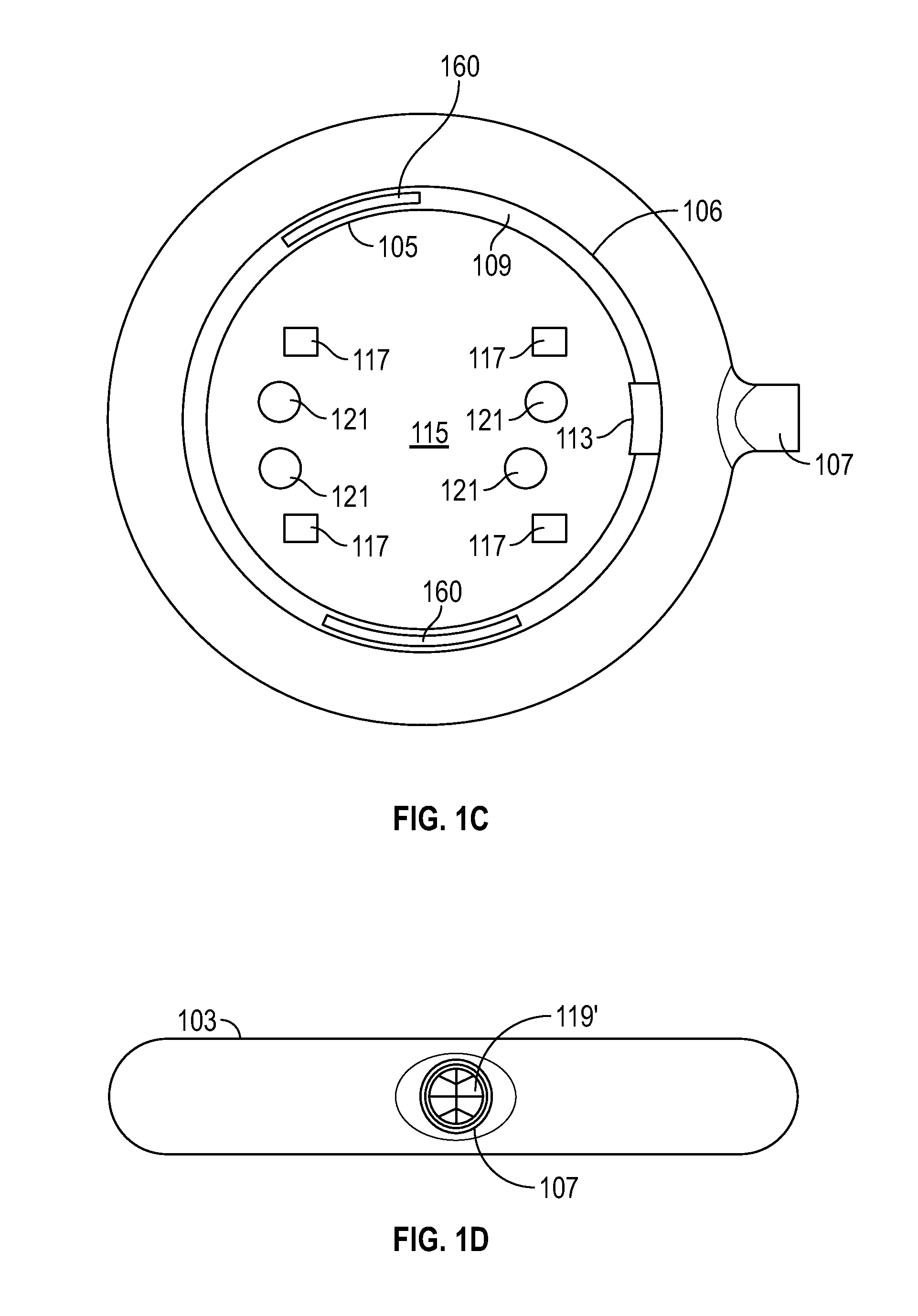
[0057]The present disclosure provides improved light delivery assemblies / systems, and associated methods for using the same. More particularly, the present disclosure provides advantageous light delivery assemblies / systems that provide light to and / or illuminate / treat pred...


PUM


Abstract

The present disclosure provides for light delivery assemblies and, more particularly to light delivery assemblies/systems that provide light to and/or illuminate/treat predetermined locations (e.g., surgical sites), and related methods of use. An exemplary light delivery assembly (e.g., a surgical site light) includes a shell/housing (e.g., a plastic shell/housing) with a cross-sectional shape similar to an inward-facing asymmetrical C. The shell/housing is shaped to be placed proximal to a site (e.g., surgical site) and emit light onto the site from a plurality of directions while inhibiting the light from radiating away from the outside of the shell/housing. Exemplary light delivery assemblies of the present disclosure can be utilized for a variety of different applications/treatments/uses (e.g., surgical applications, disinfection/sterilization especially UV in the UVC wavelength range, other UV treatment, infrared heating and treatment, therapy, IR light delivery, use of all/other wavelengths of light, etc.).

Description

CROSS REFERENCE TO RELATED APPLICATIONS[0001]This application claims the benefit of U.S. Provisional App. No. 62 / 083,811 filed Nov. 24, 2014, all of which is herein incorporated by reference in its entirety; and claims priority to and is a continuation-in-part of co-pending U.S. patent application Ser. No. 13 / 625,357 filed Sep. 24, 2012, which claims priority to Provisional App. Ser. No. 61 / 578,428 filed Dec. 21, 2011, the entire contents of each are also hereby incorporated by reference in their entireties.FIELD OF THE DISCLOSURE[0002]The present disclosure relates to light delivery assemblies / systems and, more particularly to light delivery assemblies / systems that provide light to and / or illuminate / treat predetermined locations (e.g., surgical sites / targets), and related methods of use.BACKGROUND OF THE DISCLOSURE[0003]In general, providing good / sufficient light to a site / target (e.g., surgical site) can be problematic. Not only can overhead lights be unwieldy, they can be both a ...

Claims


Application Information

Patent Timeline
Patent Type & Authority Applications(United States)
IPC IPC(8): A61N5/06
CPCA61N5/0624A61B19/5202A61N5/0625A61N5/0613A61N2005/0652A61N2005/063A61N2005/0659A61N2005/0661A61N2005/0662A61B2019/5206F21V7/00F21W2131/205A61B90/30A61B2090/309A61B2090/306
Inventor GERBER, MARK, J.RATAFIA, MANNY
Owner SPECTRUM MEDICAL TECH LLC
Why Eureka
Try Eureka