Radar System For Automated Vehicle With Phase Change Based Target Catagorization

a technology of automatic vehicles and radars, applied in the field of radar systems, can solve the problems of interference between reflected signals from each scattering center and reflected signals from other scattering centers at the receiver, and antenna-array elements could experience dissimilar interference characteristics of signals, so as to achieve the effect of being easily affected

Active Publication Date: 2016-03-24
APTIV TECH LTD
View PDF14 Cites 91 Cited by
  • Summary
  • Abstract
  • Description
  • Claims
  • Application Information

AI Technical Summary

Benefits of technology

[0010]For antenna-array configurations, the averaging of these phase differences across the antenna-array elements provides a robust phase difference value that can be used to distinguish single point and multiple near scattering center(s). As discussed, there is also phase difference variation across antenna-array elements due to the fact that relative position and / or rate of change of position differences of scattering centers are not equal for a distributed antenna-array configuration. Therefore, evaluating the slope or the variance of the slope of the phase difference across antenna-array elements can also be employed to identify between single point and multiple near scattering centers.
[0013]Determining the slope or the variance of the slope of local phase differences in the detection parameters list provides additional information that can be utilized by the tracker algorithms for object categorization according to the various on-road object groups. Prior examples of the tracker algorithms use a standard object parameters list in order to analyze their time-domain quantitative behaviors and make prediction on instantaneous object kinematics and its category or class. Examples of standard object parameters are signal amplitude, lateral and longitudinal positions and their rate-of-change of positions. These object parameters are derived from amplitude spectrum, and can be easily affected by interfering signals from multiple near-each-other scattering centers. Adding an analysis over time of the slope and / or the variance of the slope of the local phase difference in to the object parameters list will help the tracker determine additional supportive information about object size and motion profiles.

Problems solved by technology

When multiple near scattering centers of an object or objects are present, reflected signals from each scattering center interfere with reflected signals from other scattering centers at the receiver antenna.
That means that antenna-array elements could experience dissimilar interference characteristics of signals from these scattering centers due to the fact that relative phase difference changes across distributed (uniformly or non-uniformly) antenna-array elements.

Method used


Image

  • Radar System For Automated Vehicle With Phase Change Based Target Catagorization
  • Radar System For Automated Vehicle With Phase Change Based Target Catagorization
  • Radar System For Automated Vehicle With Phase Change Based Target Catagorization

Examples


Embodiment Construction

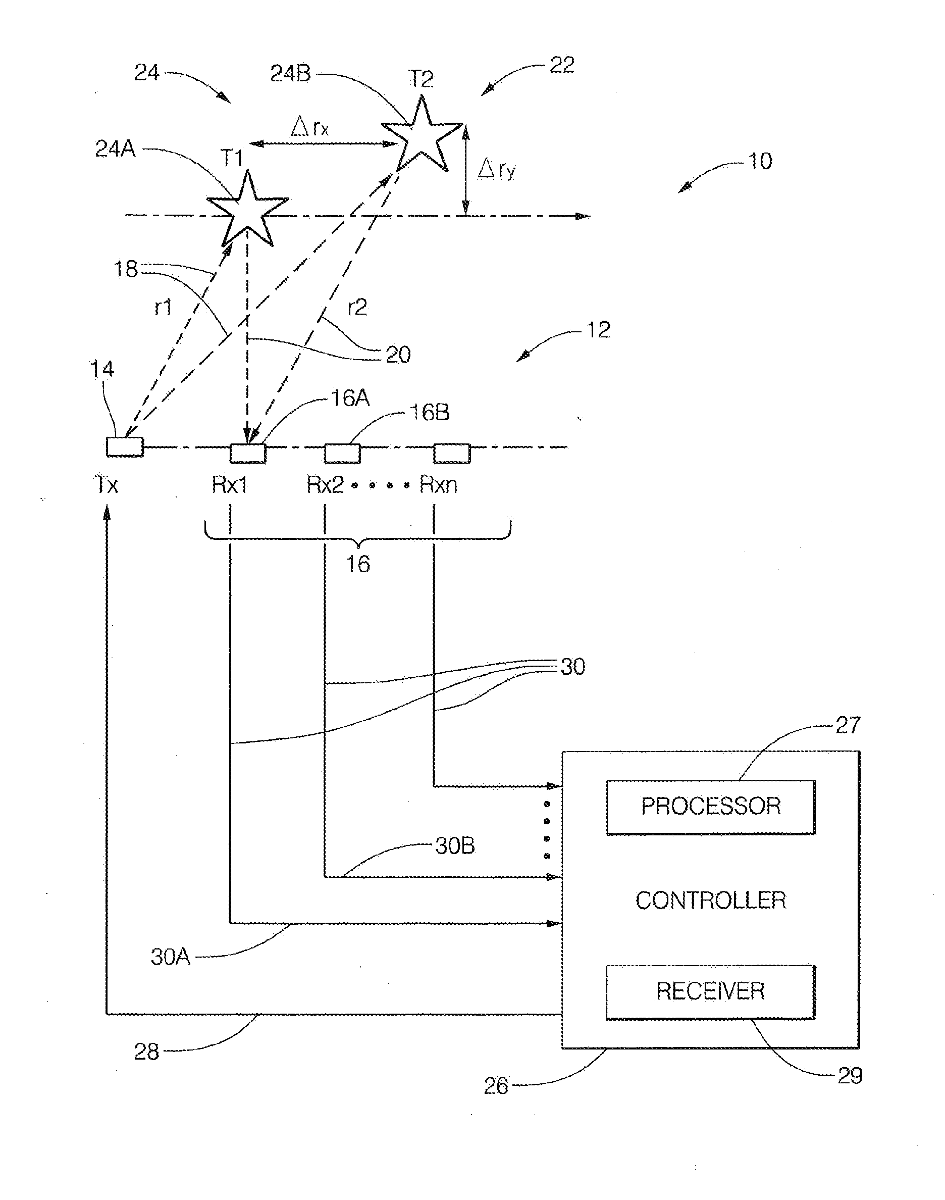
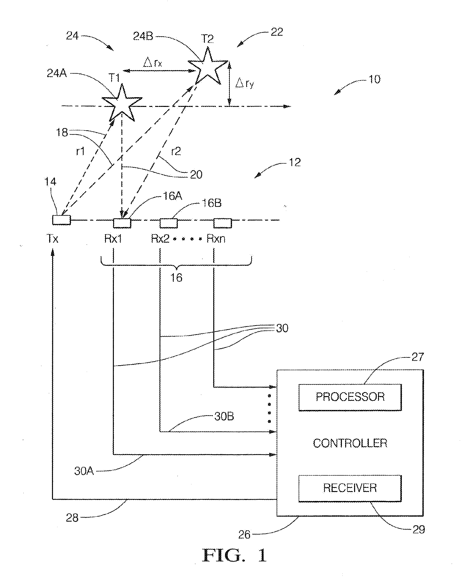
[0023]FIG. 1 illustrates a non-limiting example of a radar system, hereafter referred to as the system 10. The system 10 includes an antenna array 12 that may include a transmit-element 14, and an array of receive elements, hereafter referred to as a plurality of antennas 16. It is recognized that one or more of the antenna elements that make up the antenna array 12 could be used to both transmit a radar signal 18, and output a detected signal 30 indicative of reflected radar signals 20 reflected by a first object 24A or a second object 24B in a field-of-view 22 of the system 10. The transmit-element 14 and the plurality of antennas 16 are illustrated as distinct elements in this example only to simplify the explanation of the system 10.

[0024]The system 10 may also include a controller 26 configured to output a transmit-signal 28 to the transmit-element 14, and configured to receive detected signals 30 from each antenna, for example a first signal 30A from a first antenna 16A and a ...


PUM


Abstract

A radar system suitable for an automated vehicle includes a plurality of antennas configured to detect a reflected radar signal reflected by an object in a field-of-view of the system. Each antenna of the plurality of antennas is configured to output detected signals indicative of the reflected radar signal detected by each of the plurality of antennas. The system also includes a controller configured to receive the detected signals from the plurality of antennas, determine if the object is present in the field-of-view based on the detected signals, and determine a phase-difference between symmetrical-frequency-bins for each antenna. The symmetrical-frequency-bins are symmetrically offset from a maximum-amplitude non-coherent-integration detection-frequency-bin (max-NCI-bin). The controller is further configured to determine a classification of the object based on a time-domain-analysis of the phase differences across the plurality of antennas.

Description

CROSS-REFERENCE TO RELATED APPLICATION[0001]This application is a continuation-in-part application and claims the benefit of U.S. patent application Ser. No. 14 / 491,192, entitled RADAR SYSTEM WITH PHASE BASED MULTI-TARGET DETECTION, and filed on 19 Sep. 2014, the entire disclosure of which is hereby incorporated herein by reference.TECHNICAL FIELD OF INVENTION[0002]This disclosure generally relates to a radar system, and more particularly relates to a system that determines if a target includes more than one object based on a time-domain-analysis of the phase differences across the plurality of antennas.BACKGROUND OF INVENTION[0003]Because of system size, technology, and cost constraints, automotive radar sensors may have performance limitations with regard to discriminating two objects that have similar position and Doppler shift characteristics, or if one object has a substantially larger Radar Cross Section (RCS) than a second nearby object. Examples of two objects with similar r...

Claims


Application Information

Patent Timeline
Patent Type & Authority Applications(United States)
IPC IPC(8): G01S7/41G01S13/931
CPCG01S7/41G01S7/354G01S7/414G01S13/42G01S13/584G01S13/726G01S13/931G01S13/50G01S13/52G01S13/4454
Inventor ARAGE, ALEBEL, HASSEN
Owner APTIV TECH LTD
Why Eureka
Try Eureka