Image recording apparatus

a technology of image recording and roller, which is applied in the direction of thin material processing, article separation, article delivery, etc., can solve the problems of difficult to maintain the resin-made member in the conveyer path in a correct position, the position accuracy of the roller to convey the sheet on the base member is lowered, and the position of the roller to convey the sheet is prone to skewing or jamming in the conveyer path. , to achieve the effect of reducing the position accuracy of the roller

Active Publication Date: 2016-03-31
BROTHER KOGYO KK
View PDF3 Cites 8 Cited by
  • Summary
  • Abstract
  • Description
  • Claims
  • Application Information

AI Technical Summary

Benefits of technology

[0007]The resin-made base member may deform for a larger amount than a metal-made member when an external force is applied thereto. Therefore, it may be difficult to maintain the resin-made member in the conveyer path in a correct position. For example, if positional accuracy of a roller to convey the sheet on the base member is lowered, the sheet being conveyed by the roller may skew or jam in the conveyer path. The positional inaccuracy in the members that form the conveyer paths may be caused more easily when the resin-made base member, in which the conveyer paths are formed, is thinner.
[0008]The present disclosure is advantageous in that an image recording apparatus capable of recording an image on either side of a sheet, in which positional accuracy of parts to be arranged on the conveying path may be prevented from being lowered while positions of the parts may be defined by a position of the resin-made base member, is provided.

Problems solved by technology

Therefore, it may be difficult to maintain the resin-made member in the conveyer path in a correct position.
For example, if positional accuracy of a roller to convey the sheet on the base member is lowered, the sheet being conveyed by the roller may skew or jam in the conveyer path.

Method used


Image

  • Image recording apparatus
  • Image recording apparatus
  • Image recording apparatus

Examples


modified examples

[0125]Although an example of carrying out the invention has been described, those skilled in the art will appreciate that there are numerous variations and permutations of the image recording apparatus that fall within the spirit and scope of the invention as set forth in the appended claims. It is to be understood that the subject matter defined in the appended claims is not necessarily limited to the specific features or act described above. Rather, the specific features and acts described above are disclosed as example forms of implementing the claims.

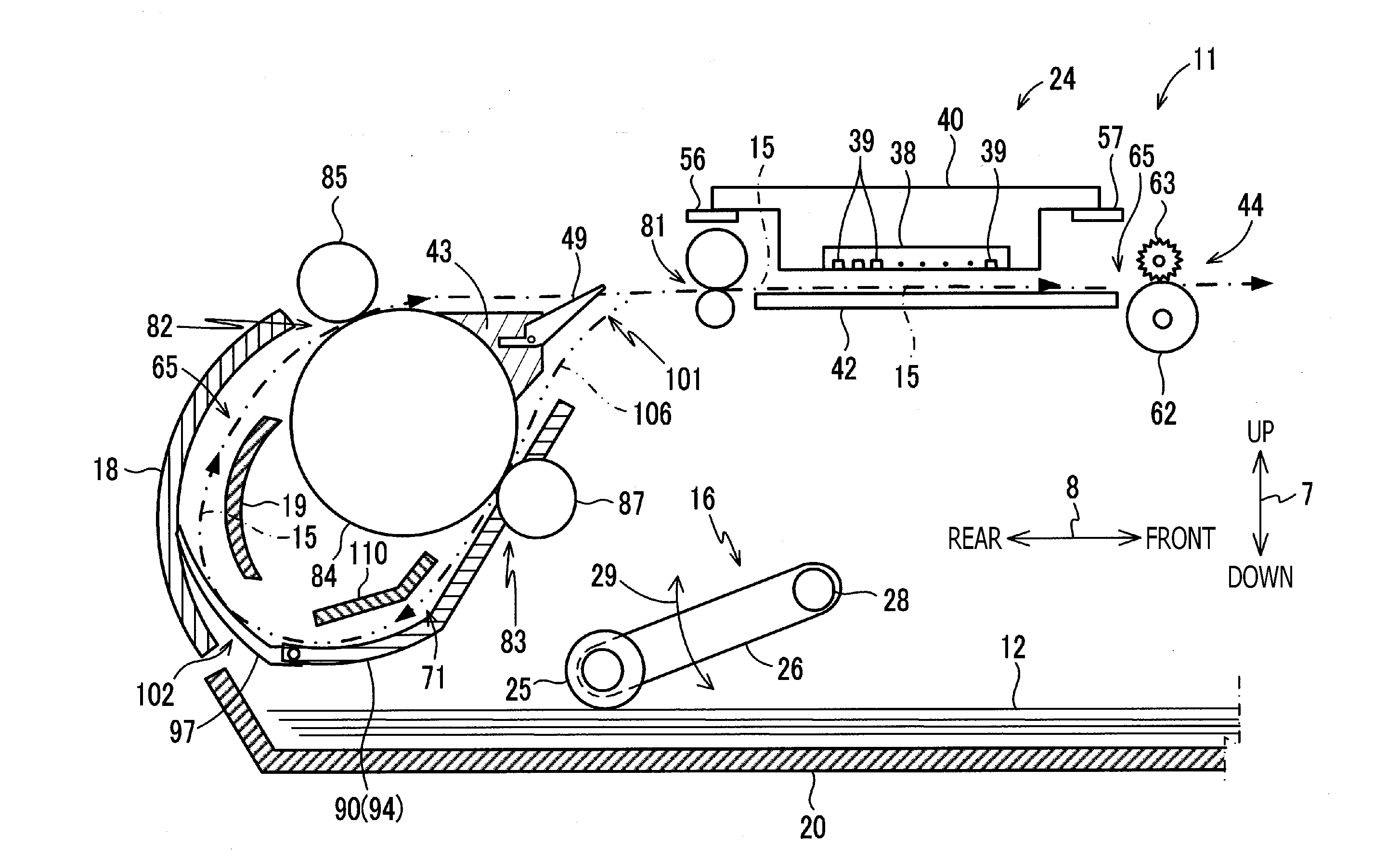
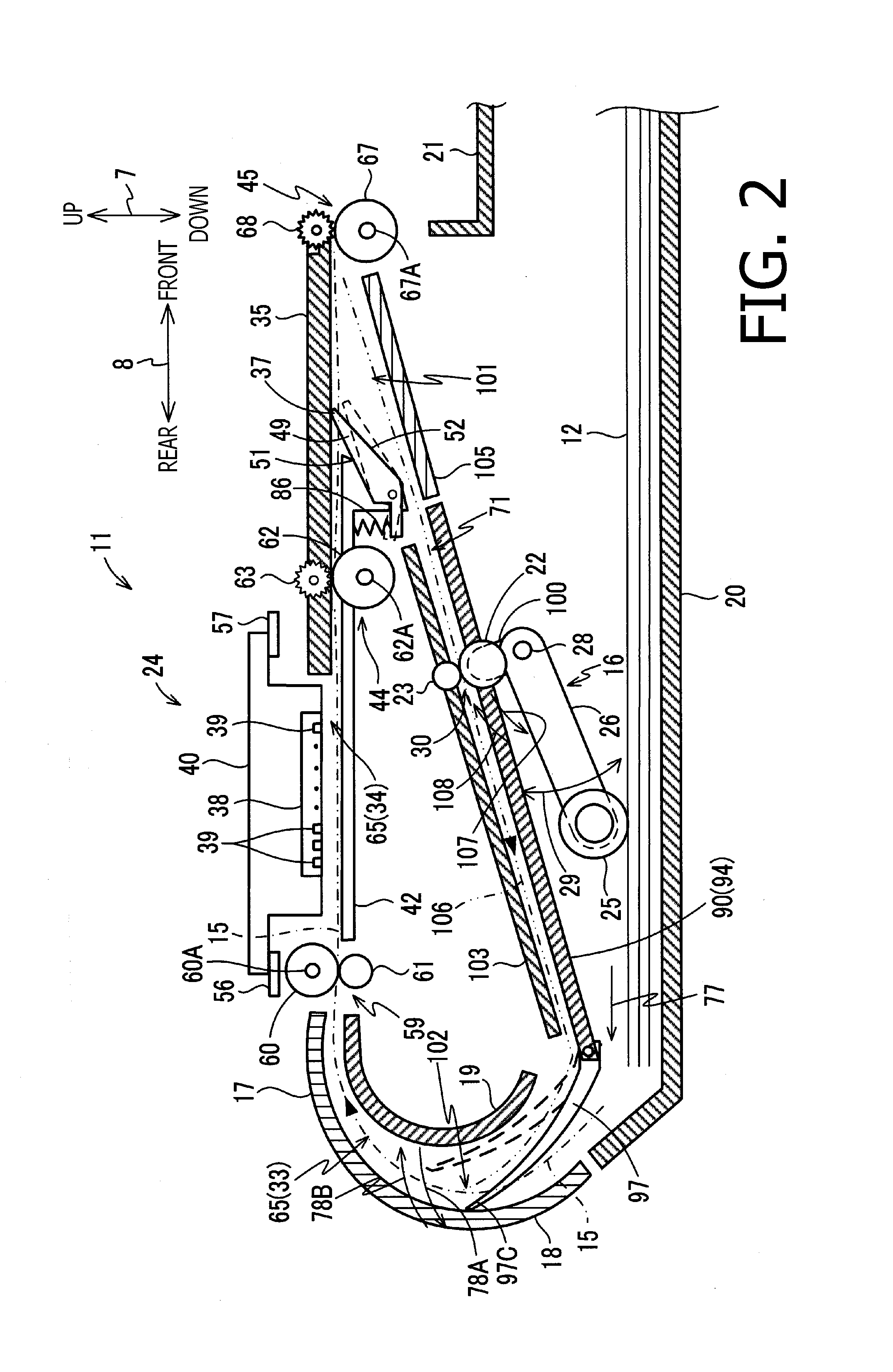
[0126]For example, the feeder roller 25 and the return-conveyer roller 22 may not necessarily be rotated by the rotation of the same drive shaft 28 but may be rotated by rotation of different drive shafts.

[0127]For another example, the recording sheet 12 in the inverting path 71 may not necessarily be guided on the plurality of ribs 96, which are formed on the upper side of the rearward section 94 of the base member 90. For example,...


PUM

PropertyMeasurementUnit
driving forceaaaaaaaaaa
sizeaaaaaaaaaa
external forceaaaaaaaaaa

Abstract

An image recording apparatus, including a tray configured to support a sheet; a chassis defining a first conveyer path, in which the sheet on the tray is conveyed in a first conveying direction, and a second conveyer path, through which the sheet is conveyed in a second conveying direction through a branch point to be inverted to reenter the first conveyer path through a merging point; a base member integrally formed of resin and including a guiding section to define a form of a part of the second conveyer path; a recording unit to record an image on the sheet conveyed in the first conveyer path; a drive shaft supported by the base member; and a return-conveyer roller disposed in the second conveyer path and configured to convey the sheet to be guided on the guiding section in the second conveying direction by rotation of the drive shaft, is provided.

Description

CROSS REFERENCE TO RELATED APPLICATION[0001]This application claims priority from Japanese Patent Application No. 2014-194543, filed on Sep. 25, 2014, the entire subject matter of which is incorporated herein by reference.BACKGROUND[0002]1. Technical Field[0003]The present invention relates to an image recording apparatus capable of recording an image on either side of a sheet.[0004]2. Related Art[0005]An image recording apparatus capable of recording an image on either side of a sheet is known. The image recording apparatus may have a first conveyer path, along which a recording unit is disposed, and a second conveyer path, which inverts the sheet with the image recorded on a first side and directs the inverted sheet to the first conveyer path so that another image may be recorded on second side of the sheet. In the first and second conveyer paths, a plurality of rollers may be disposed to convey the sheet.[0006]Meanwhile, in order to reduce a size, a quantity of parts, and manufac...

Claims


Application Information

Patent Timeline
Patent Type & Authority Applications(United States)
IPC IPC(8): B65H15/00B65H1/04B65H5/06B65H5/26B65H29/58
CPCB65H15/00B65H5/068B65H29/58B65H5/26B65H1/04B65H85/00B65H3/0669B65H5/062B65H2403/40B65H2403/50B65H2301/33312B65H2403/942B65H2404/632B65H2801/06B65H5/38
Inventor SANO, IWANEIIJIMA, SHOTA
Owner BROTHER KOGYO KK
Why Eureka
Try Eureka