Arrangement having a seal

a technology of arrangement and sealing, applied in the direction of machines/engines, mechanical equipment, liquid fuel engines, etc., can solve the problems of difficult sealing installation of end-face covers, difficult removal and installation of heavy components, etc., and achieve the effect of simple installation procedure and good sealing

Inactive Publication Date: 2016-03-31
SIEMENS AG
View PDF3 Cites 4 Cited by
  • Summary
  • Abstract
  • Description
  • Claims
  • Application Information

AI Technical Summary

Benefits of technology

[0009]The seal carrier, according to aspects of the invention, having the radial and axial grooves which extend in the circumferential direction and which seal, with the seals introduced there, respectively against a radial or axial surface of the casing or of the cover, first allows the cover to be installed in the casing without a seal so as to prevent damage to the seal in this installation step. The seal carrier with the seals located therein is substantially lighter, and therefore simpler to install, than the cover. Exactly controlled and, where possible, manual installation of the seal carrier can thus take place simply and without damage. The invention provides that the cover is arranged axially further inside the casing than the seal carrier, such that the seal carrier bears with the seals axially against the cover from the outside. This makes it simple to monitor the sealing function and, if it is necessary to replace the seal, this can take place without removing the cover. Furthermore, the cover for the seal serves as a thermal buffer in the event that the fluid present in the pressurized container or casing is a particularly hot or cold fluid.
[0013]Particularly advantageously, it is expedient if the suction line extends from the axial suction groove through the seal carrier to the radial suction groove and continues from the radial suction groove through the casing. It is thus possible to provide just a single suction which opens in the suction line and to simultaneously secure, with this suction, the radial seal and the axial seal in particular against egress of toxic or explosive gases. Expediently, the seal carrier is made from a particularly high-strength material. Particularly, the seal carrier itself is made of metal so as to ensure high dimensional stability and chemical resistance with respect to possible aggressive process fluids.
[0014]Expediently, the arrangement according to the invention can comprise fixing elements for fixing the cover to the casing, wherein the fixing elements comprise a fixing ring which extends in the circumferential direction and is segmented in the circumferential direction, and which bears axially against the seal carrier and is directly or indirectly fixed and / or supported on the casing. Such a fixing method, also known as a shear ring, allows the cover and the seal carrier to be fixed to the casing in a space-saving manner, and simultaneously permits high fixing forces.
[0016]The two radially inwards-extending projections form, with a section of the casing located axially between these projections, a bracket extending in the circumferential direction which, together with the fixing elements, exerts an axial pre-stress force on the assembly of the seal carrier with the seals and the cover. A simple advantage of this arrangement lies in the possibility that the pressure within the casing is higher than the ambient pressure and thus the cover is pressed against the axial seal of the seal carrier, such that the seal effect is reinforced with increasing internal pressure.

Problems solved by technology

Damage to the sealing faces can make it necessary to undertake onerous removal and installation of heavy components.
In particular in the case of casings having what is termed a barrel-type construction—that is to say casings which have no horizontal parting joint or parting joint which extends in the longitudinal axis of the cylindrical casing—sealing installation of an end-face cover is particularly difficult.
The end-face cover is generally very heavy and requires a load-bearing guide when inserting the cover into the barrel casing, if the cover does not simply bear against the end face but is at least partially surrounded in the circumferential direction by the jacket-shaped casing.
If the cover is at the same time the carrier for the seals, intended or unintended contact between the seal and the casing can damage the seal, because, in said contact, the cover overloads the seal because of the great weight and relative inaccessibility of the former in the installation situation.

Method used


Image

  • Arrangement having a seal
  • Arrangement having a seal
  • Arrangement having a seal

Examples


Embodiment Construction

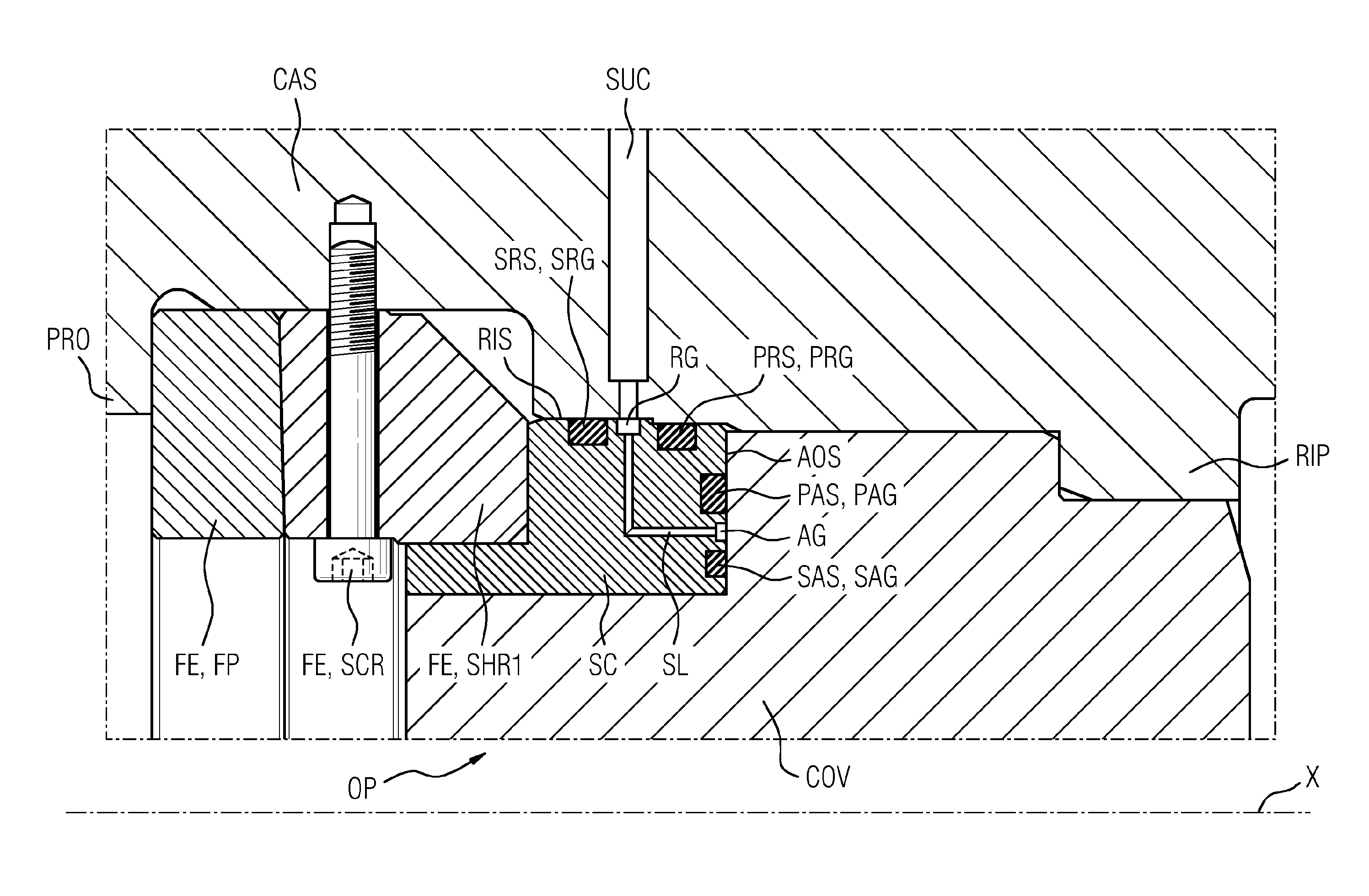
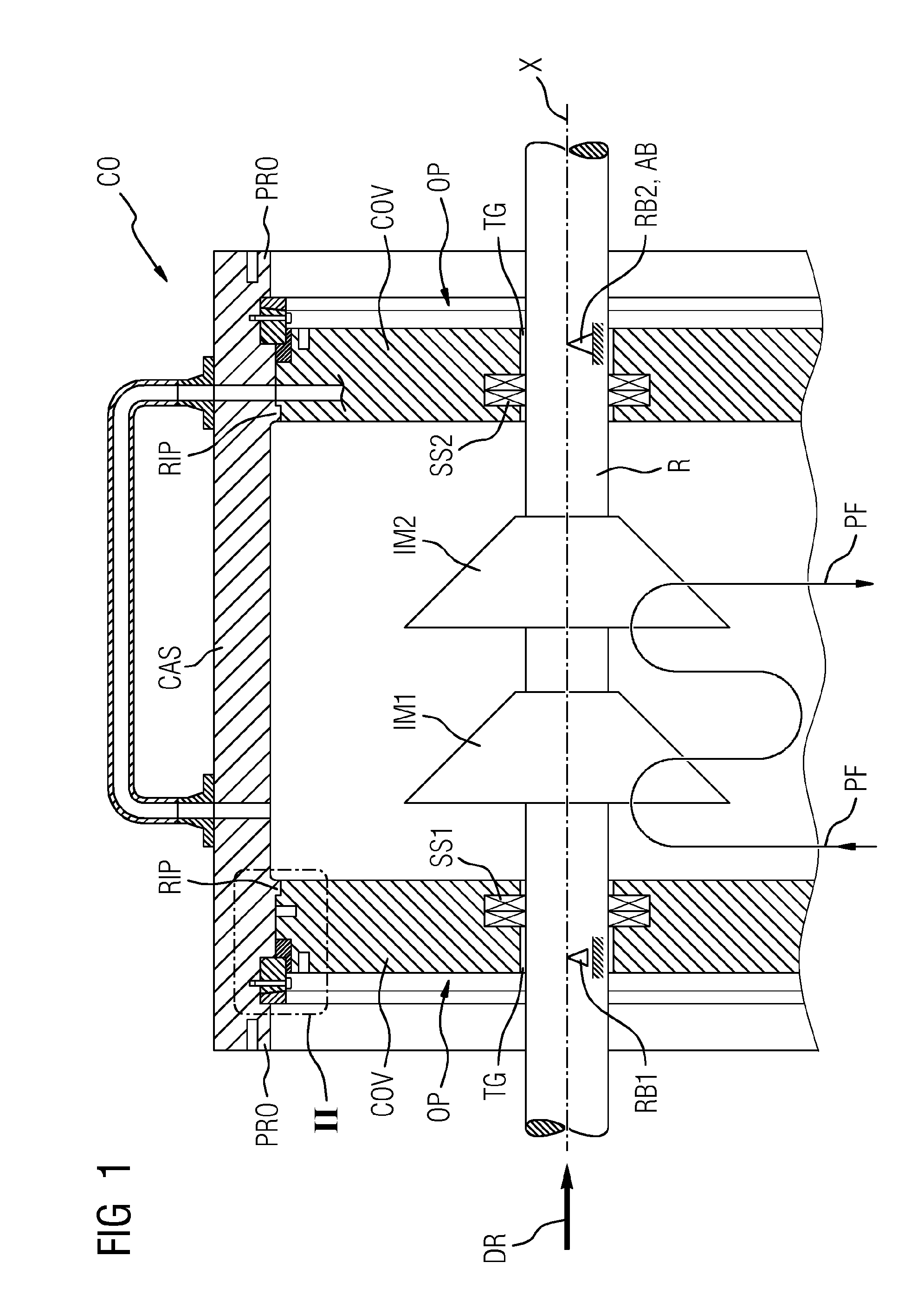
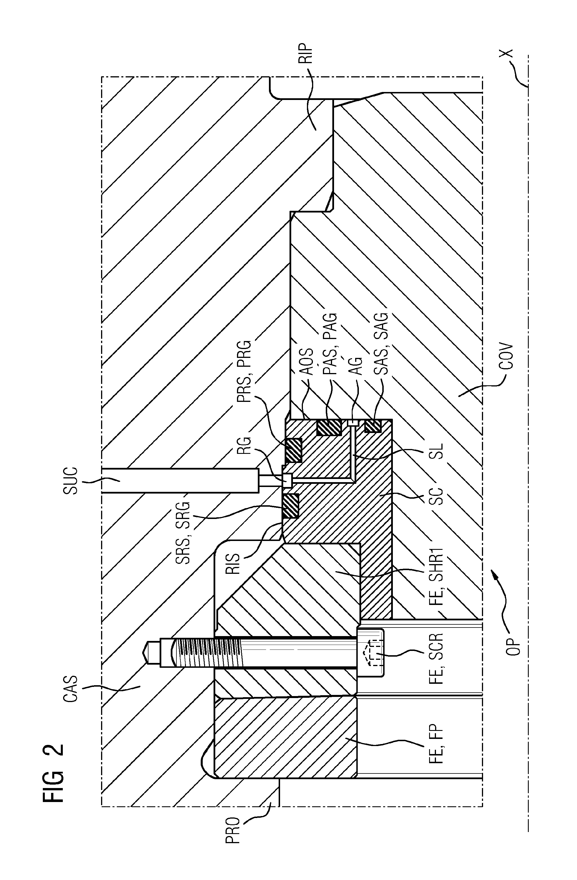
[0021]The schematic representation of FIG. 1 shows an axial section through an arrangement according to the invention having a seal, with FIG. 2 showing a detail portion of FIG. 1, labeled II.

[0022]An exemplary field of application for the invention is use in turbomachines, in particular turbocompressors or turbo-expanders, as is represented in FIG. 1 with reference to a compressor. The compressor CO shown in FIG. 1 comprises a rotor R which extends along a longitudinal axis X of a casing CAS and is equipped with two impellers, a first impeller IM1 and a second impeller IM2. FIG. 1 indicates that a process fluid PF passes through the compressor by means of the two impellers IM1, IM2 and then leaves the casing CAS. The casing CAS is a casing of what is termed barrel construction, i.e. the casing CAS does not have a parting joint parallel to the longitudinal extent of the casing CAS. In essence, the casing CAS shown consists of a jacket-shaped part and is closed at end-face openings O...


PUM


Abstract

An arrangement having a seal, includes: a casing, a cover, and at least one seal. In order to ensure damage-free installation of the cover and simultaneously simplify the installation process itself, as well as to guarantee good sealing, the arrangement has a seal carrier, the seal carrier has a first radial groove extending in the circumferential direction and having a radial depth direction, in which first radial groove a first radial seal is arranged, which seals against a radially inward surface of the casing, the seal carrier has a first axial groove extending in the circumferential direction and having an axial depth direction, in which first axial groove a first axial seal is arranged, which seals against an axial surface of the cover.

Description

CROSS REFERENCE TO RELATED APPLICATIONS[0001]This application is the US National Stage of International Application No. PCT / EP2014 / 058058 filed Apr. 22, 2014, and claims the benefit thereof. The International application claims the benefit of German Application No. DE 102013208357.2 filed May 7, 2013. All of the applications are incorporated by reference herein in their entirety.FIELD OF INVENTION[0002]The invention relates to an arrangement having a seal, comprising: a casing of a turbomachine, a cover, at least one seal, wherein the casing has a longitudinal axis, wherein the cover is introduced into the casing in the axial direction in order to close an end-face opening of the casing.BACKGROUND OF INVENTION[0003]An exemplary field of application for this technology is that of turbomachines, in particular turbocompressors. The technology may in principle also be used on other pressurized containers. Turbomachines, because of their construction, have at many points separating faces...

Claims


Application Information

Patent Timeline
Patent Type & Authority Applications(United States)
IPC IPC(8): F16J15/06F04D29/08
CPCF16J15/061F04D29/08F16J13/08F16J15/004F04D17/12F04D19/02F04D29/083F04D29/4206F04D29/522
Inventor ZACHARIAS, WOLFGANG
Owner SIEMENS AG
Why Eureka
Try Eureka