
Developing unit

a technology of developing sleeves and developing sleeves, applied in the field of developing sleeves, can solve the problems of overflowing of developers, unstable coating properties of developers, and unstable properties of coating developing sleeves with developers

Active Publication Date: 2016-03-31
CANON KK
View PDF3 Cites 2 Cited by
  • Summary
  • Abstract
  • Description
  • Claims
  • Application Information

AI Technical Summary

Benefits of technology

The invention prevents the developer from entering the second chamber while the coating of the developer on the developer bearing member is stabilized.

Problems solved by technology

Then, a coating property of the developer easily becomes unstable, and for example, the developing sleeve is unevenly coated with the developer.
Therefore, there is a possibility that dragging, in which the developer in the second chamber is dragged by the developing sleeve, occurs and the property of coating the developing sleeve with the developer becomes unstable.
In addition, there is also a possibility that overflowing of the developer occurs because the developer on the developing sleeve cannot be sufficiently introduced into the second chamber.

Method used


Image

  • Developing unit
  • Developing unit
  • Developing unit

Examples


first embodiment

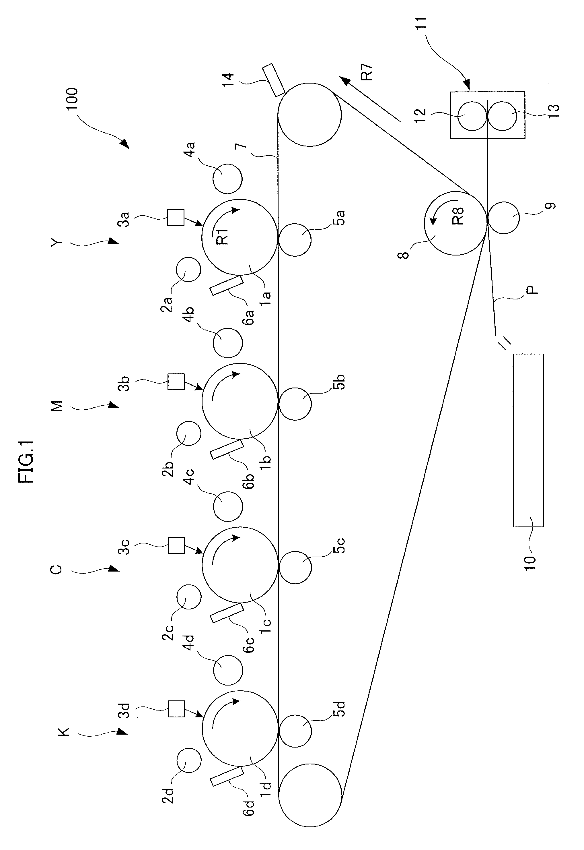
[0026]A first embodiment will be described with reference to FIGS. 1 to 8. First, a description will be given of an outline configuration of an image forming apparatus according to this embodiment with reference to FIG. 1.

[Image Forming Apparatus]

[0027]An image forming apparatus 100 is a full-color printer based on the electro-photographic system, which is provided with four image forming stations Y, M, C, and K.

The image forming apparatus 100 forms a toner image (image) on a recording medium P in response to an image signal from a host device such as an document reading device (not shown) that is connected to an apparatus body or a personal computer that is connected to the apparatus body so as to communicate with the apparatus. Examples of the recording medium include sheet materials such as paper, a plastic film, and cloth.

In addition, the image forming stations Y, M, C, and K form yellow, magenta, cyan, and black toner images, respectively.

[0028]It is noted that the four image f...

example 1

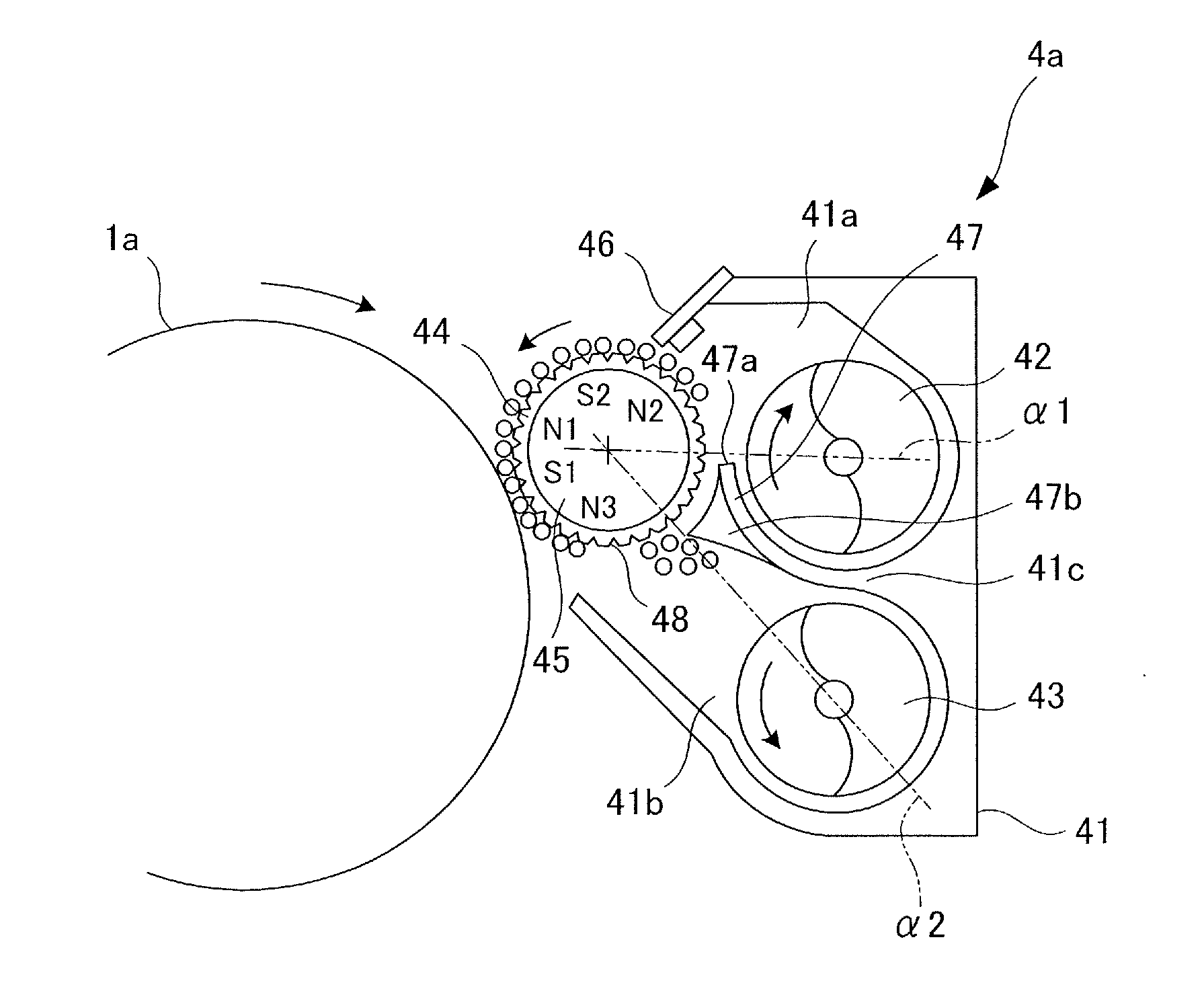
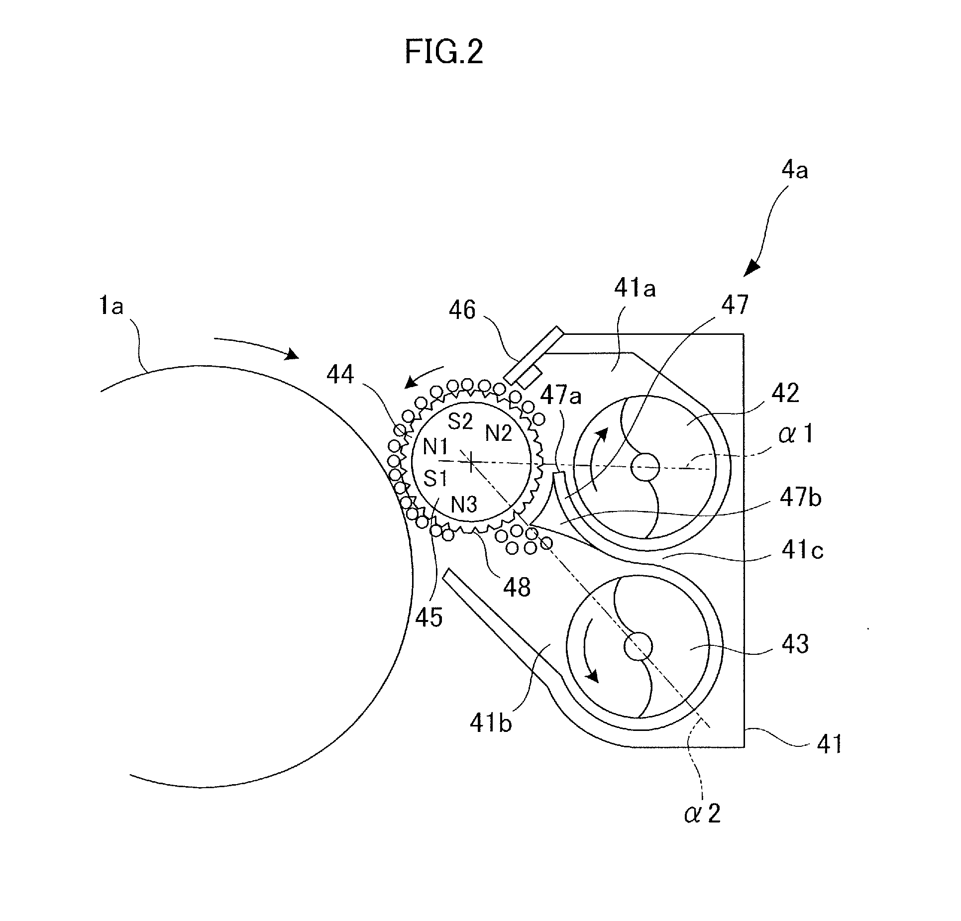
[0066]Next, a description will be given of an experiment conducted in order to confirm the effect of the aforementioned embodiment. In the experiment, Example 1 of the configuration according to the embodiment described above with reference to FIG. 2 and the like was compared with configurations in Comparative Examples 1 and 2 illustrated in FIGS. 5 and 6. First, a description will be given of a configuration in Comparative Example 1 with reference to FIG. 5. In the case of a developing unit 400 in Comparative Example 1, conveyability of a surface of a developing sleeve 440 was secured by performing random ruggedness processing by blast processing on the surface of the developing sleeve 440 to obtain high surface roughness. In addition, a height of an apex 470a of a partitioning wall 410c between the first conveyor screw 42 and the developing sleeve 440 was located at a position above the zero-gauss zone, in which the magnetic force formed by the magnet roller 45 was substantially z...

second embodiment

[0075]A description will be given of a second embodiment of this disclosure with reference to FIGS. 8 to 10. The developing unit 40a according to the embodiment relates to a configuration that employs a multiple-stage developing system by which it is possible to increase opportunities of development. Specifically, predetermined density is secured by using a plurality of developing sleeves. More specifically, two developing sleeves are used in this embodiment. Such a configuration is preferably used in response to a further increase in speed of the image forming apparatus. Since the other configurations and the effects are the same as those of the aforementioned first embodiment, depiction of the same configurations will be omitted or the same reference numerals will be provided thereto for omitting or simplifying the descriptions. It is noted that hereinafter, differences from the first embodiment will be mainly described. Although a description will be given of the developing unit ...


PUM


Abstract

A multipolar magnet is arranged inside a developer bearing member. A partitioning wall is arranged such that an apex position thereof is located between the developer bearing member and a first conveying member, and is extended up to a position which is located below an upper end position of a zero-gauss zone. A plurality of concaved portions is formed on the surface of the developer bearing member at an interval. Each of the plurality of concaved portions has such an opening shape that a maximum diameter of an inscribed circle is equal to or greater than a diameter of an average grain size of a carrier, and is formed such that the carrier with the average grain size is able to enter each of the concaved portions by a depth that is equal to or greater than a radius thereof.

Description

BACKGROUND OF THE INVENTION[0001]1. Field of the Invention[0002]This disclosure relates to a developing unit that develops a latent image formed on an image carrier by an electro-photographic system, an electrostatic recording system, or the like to form a visible image.[0003]2. Description of the Related Art[0004]In an image forming apparatus using an electro-photographic system in the related art, an electrostatic latent image that is formed on an image bearing member, such as a photosensitive drum, is developed by a developing unit by using a toner. As such a developing unit, a developing unit adapting a vertical agitating and function separation type is known. This vertical agitating and function separation type developing unit is configured to array a first chamber for supplying a developer to a developing sleeve as a developer bearing member and a second chamber for collecting the developer from the developing sleeve vertically. In a case of a configuration disclosed in JP-A-5...

Claims


Application Information

Patent Timeline
Patent Type & Authority Applications(United States)
IPC IPC(8): G03G15/09
CPCG03G15/0921G03G15/0928
Inventor NOGUCHI, AKIHIRO
Owner CANON KK
Features
  • Generate Ideas
  • Intellectual Property
  • Life Sciences
  • Materials
  • Tech Scout
  • Unparalleled Data Quality
  • Higher Quality Content
  • 60% Fewer Hallucinations
Learn More