applicator

Inactive Publication Date: 2016-04-07
MITSUBISHI PENCIL CO LTD
View PDF2 Cites 5 Cited by
  • Summary
  • Abstract
  • Description
  • Claims
  • Application Information

AI Technical Summary

Benefits of technology

[0042](4) In the present invention, it is preferable that the cavity part contains a filler that has been made viscous by a thickener.
[0043]When using a thickener to form a gel-like filler and fill the cavity part, the agent couples with the filler due to gravity to form a gel-like lump.
[0044]Use of various kinds of thickeners, either water-based or oil-based, facilitates production of gel-like fillers of different softness.
[0046](5) In the present invention, it is preferable that the cavity part contains air, and the air is tightly sealed in the cavity part by adjusting the thickn

Problems solved by technology

Though use of the fingers for application facilitates the liquid to spread uniformly, there is the problem that the fingers dirty.
Use of cotton swabs makes application work easy, but entails problems of uneven application and adhesion of fibers.
When sponge is used as the applying part, the liquid permeates over the sponge surface and is likely to produce spoils on the applied surface, causing hygienic problems.
Further, there is also another problem that the component easy to permeate into sponge, such as a solvent of the liquid, is soaked into the sponge, changing the composition of the liquid retained in the applying part.
A brush is an application body (applying part) formed of a bundle of fibers, hence it leaves fiber traces on the applied surface upon application, hence makes it difficult to apply the liquid thinly and uniformly.
As a result, when the liquid is applied by moving the application body under this condi

Method used


Image

  • applicator
  • applicator
  • applicator

Examples


Example

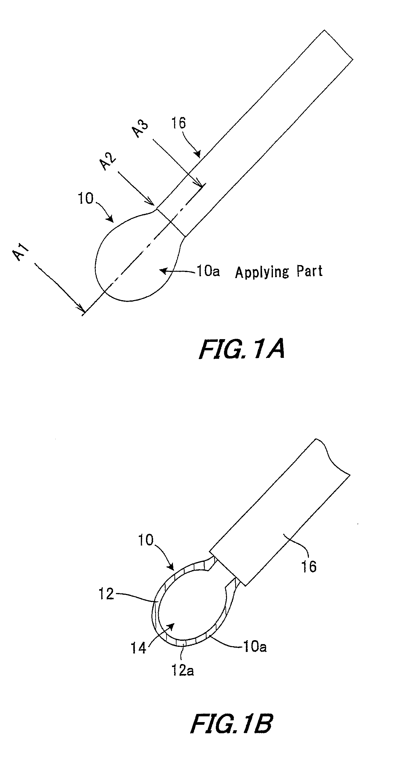
[0081]FIG. 1 is an illustrative view of the applicator according to the first embodiment of the present invention.

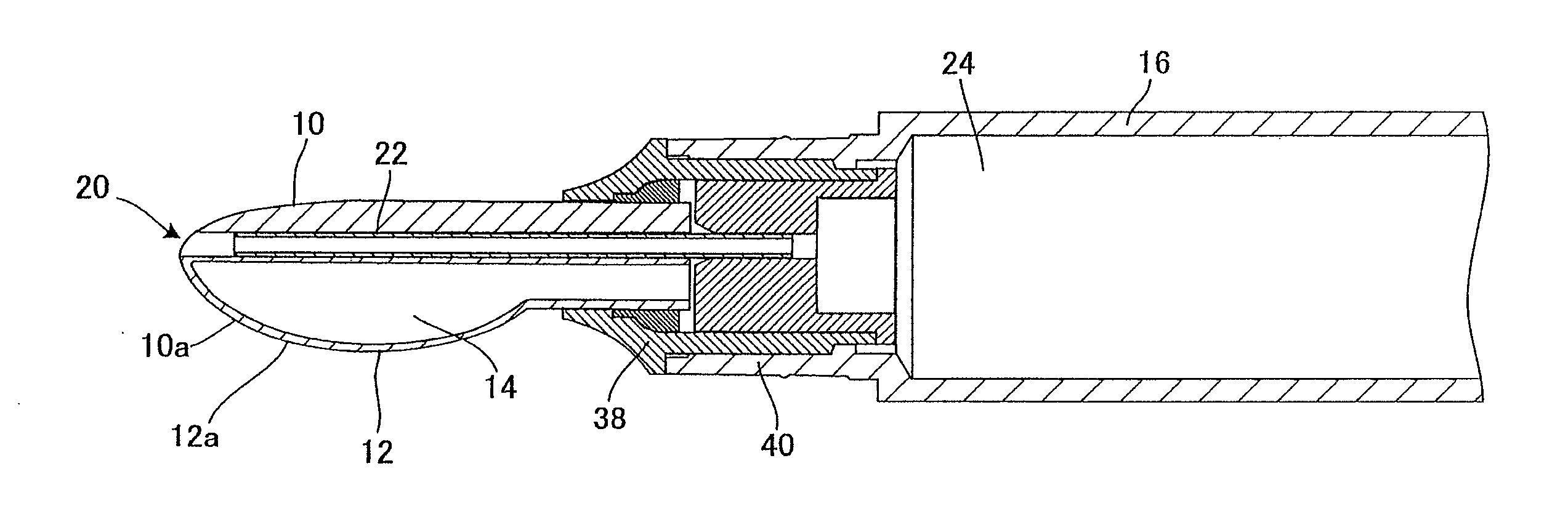
[0082]The applicator according to the first embodiment is an applicator for applying an application liquid on a surface of an object to be applied on by means of an application body 10.

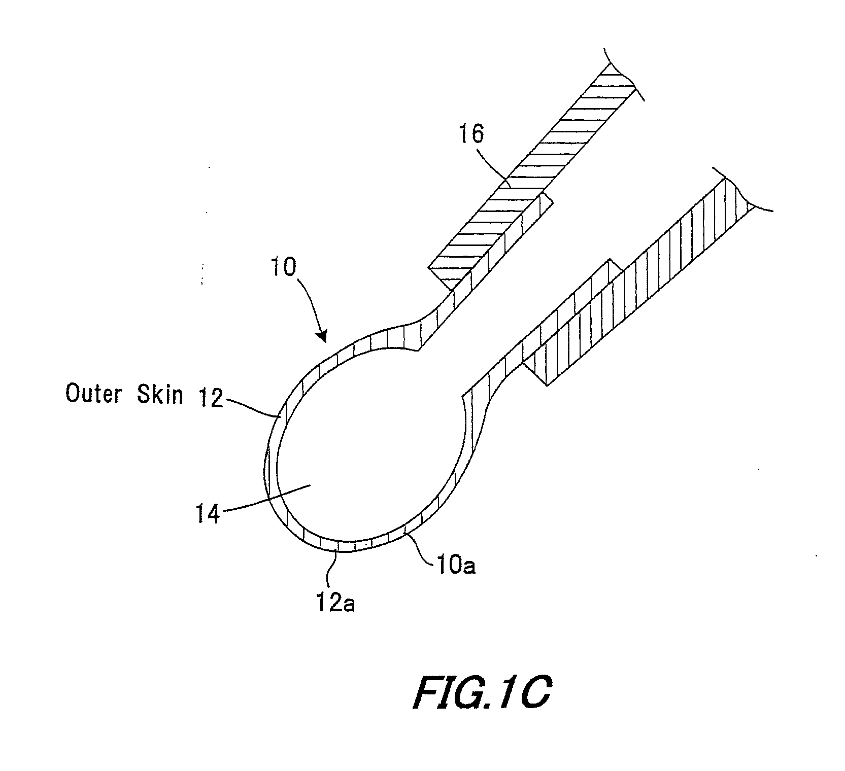
[0083]The application body 10 has a membranous part 12 that easily deforms at the time of application and a cavity part 14 enclosed by the membranous part.

[0084]The application body 10 is configured so that when an applying surface 12a of the membranous part 12 comes into contact with the surface to be applied on, a contact surface of the membranous part 12 fits closely following a contact area of the surface to be applied on by virtue of the pressure of the membranous part 12 onto the contact area of the applied surface.

[0085]Specifically, as shown in FIG. 1 the application body 10 is formed of the membranous part 12 as an outer skin and the cavity part 14 alone and is a flexible bag-like...

Example

[0087]The applicator according to the second embodiment will be described.

[0088]FIG. 2 is the illustrative view of the application body used for the applicator according to the second embodiment. FIG. 3 is the illustrative view of the entire applicator. FIG. 4 is the illustrative view showing use states of the applicator.

[0089]As shown in FIG. 2, an application body 10 according to the second embodiment has: a membranous part 12 forming an applying surface 12a; a rigid reinforcement part 18 formed thicker than the applying surface 12a; and a liquid delivery hole 20 formed between the former two parts. The rigid reinforcement part 18 is formed on the opposite side of the applying surface 12a of the membranous part 12 with respect to the liquid delivery hole 20. The reinforcement part 18 is provided so that the application body 10 as a whole will not deform when the applicator is used for application.

[0090]The application body 10 is molded of a liquid silicone (either LIM type or mill...


PUM


Abstract

To provide an applicator with an application body that is nonabsorbent and can uniformly spread and apply an application liquid over the surface to be applied on without scraping the applied liquid during application. The application body includes a membranous part that is easily deformable in applying liquid, and a cavity part enclosed by the membranous part, and constructed such that when the applying surface of the membranous part comes into contact with the surface to be applied on, the contact surface of the membranous part fits closely following the surface to be applied on by the pressure of the membranous part acting onto the contact surface of the surface to be applied on.

Description

[0001]This Nonprovisional application claims priority under 35 U.S.C. §119 (a) on Patent Application No. 2014-203210 filed in Japan on 1 Oct. 2014, the entire contents of which are hereby incorporated by reference.BACKGROUND OF THE INVENTION[0002](1) Field of the Invention[0003]The present invention relates to an applicator for cosmetics and medical use, which includes a container for applying a liquid and is required to uniformly apply a liquid of a relatively high viscosity and the like.[0004](2) Description of the Prior Art[0005]Conventionally, there have been diverse proposals of applicators for applying liquid content solutions.[0006]For example, there have been applicators that simply apply and spread a liquid with a cotton swab or sponge, and applicators that deliver a liquid and spread the liquid by its applying part of the container, disclosed in Japanese Patent Application Laid-open 2010-42046 (:Patent Document 1) and Japanese Patent Application Laid-open 2007-130157 (:Pat...

Claims


Application Information

Patent Timeline
IPC IPC(8): A45D34/04A45D40/28A61F13/40
CPCA45D34/04A45D40/28A61M35/006A45D34/042A46B9/005A46B11/0006A46B11/0055A46B2200/1046
Inventor NAKAJIMA, NOBUYUKIOOBA, SHIGEKIHASEGAWA, TOMOKONAGASAKA, YUUYATAKACHIYO, KEIICHIRO
Owner MITSUBISHI PENCIL CO LTD
Why Eureka
Try Eureka