Controlled ingrowth feature for antimigration

Active Publication Date: 2016-04-07
BOSTON SCI SCIMED INC
View PDF2 Cites 15 Cited by
  • Summary
  • Abstract
  • Description
  • Claims
  • Application Information

AI Technical Summary

Benefits of technology

[0010]The cover may be non-porous. The cover may be attached to the scaffolding outer surface. The cover may have a length equal to the longitudinal length of the scaffolding. The cover may form the prosthesis outer surface. The c

Problems solved by technology

Migration of the stent from its initial

Method used


Image

  • Controlled ingrowth feature for antimigration
  • Controlled ingrowth feature for antimigration
  • Controlled ingrowth feature for antimigration

Examples


example 1

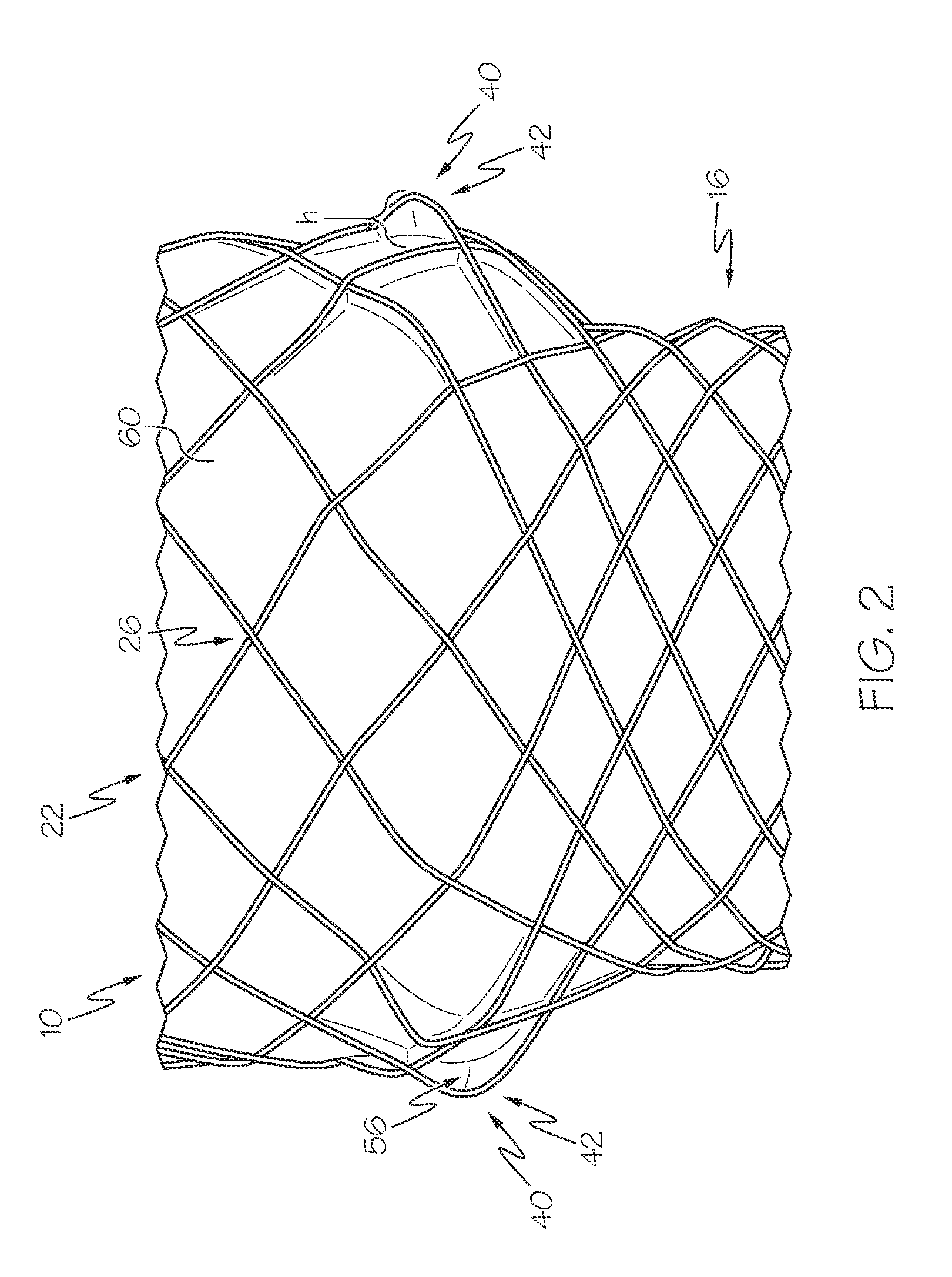
[0138]FIG. 2 shows an example of a prosthesis 10 with at least protruding element 40. Specifically, the prosthesis 10 has a single layer of scaffolding 18 in the form of a mesh 22 with a protruding scaffolding filament section 42; and a cover 60.

[0139]The prosthesis has a longitudinal length of 102 mm. The end regions of the prosthesis 10 have a greater diameter than the middle region, with the end regions having a diameter of 30 mm, and the middle region having a diameter of 23 mm.

[0140]The scaffolding 18 is formed from 24 scaffolding filaments 20 each having a diameter of 0.009 mm, and comprises Nitinol. The scaffolding filaments 20 are braided at a uniform braiding angle.

[0141]The cover 60 is non-porous.

[0142]In this example, each scaffolding filament 20 with a right hand orientation has a protruding scaffolding filament section 42 extending between two scaffolding filament crossings 26 immediately adjacent one another, and each protruding scaffolding filament section 42 has a cl...

example 2

[0143]FIG. 9 shows another example of a prosthesis 10 with at least one controlled tissue ingrowth feature 40. Specifically, the prosthesis 10 has a single layer of scaffolding 18 in the form of a mesh 22 with two protruding mesh regions 44a, 44b; and a cover 60.

[0144]The prosthesis 10 has a diameter of 23 mm and a longitudinal length of 150 mm. The prosthesis 10 may have a uniform diameter except for the protruding mesh regions 44. However, the ends of the prosthesis, not shown in FIG. 9, may have a greater diameter than the uniform diameter section shown in FIG. 9. The scaffolding 18 is formed from 24 scaffolding filaments 20 each having a diameter of 0.008 mm and comprises Nitinol.

[0145]The cover 60 is non-porous and has a thickness of 40 μm.

[0146]Each protruding mesh region 44a, 44b forms a circumferential ring that extends around the entire circumference of the prosthesis; has a gap height h of 1 mm; and a longitudinal distance d of 10 mm. A longitudinal distance of 40 mm separ...

example 3

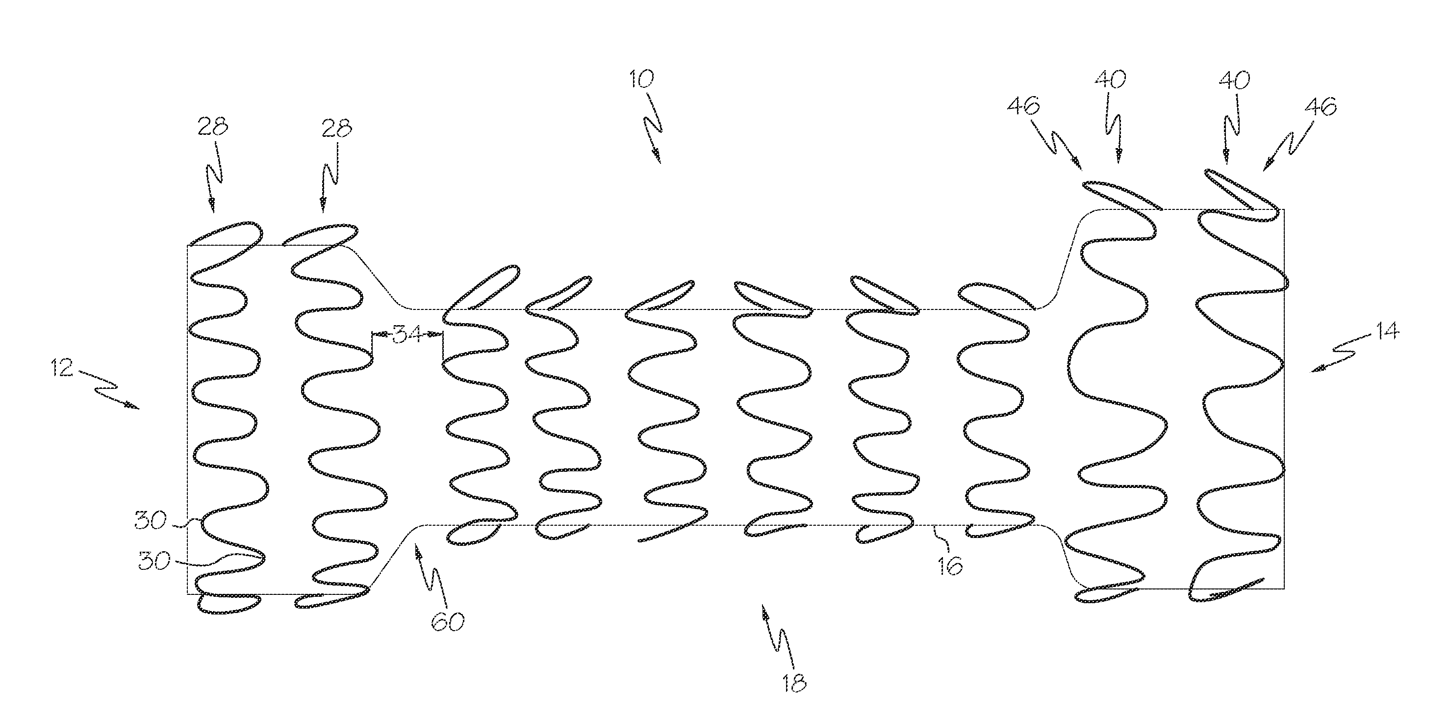
[0147]FIG. 10 shows another example of a prosthesis 10 with at least one protruding element 40. The prosthesis 10 shown in FIG. 10 is constructed and arranged for implantation in the esophagus.

[0148]The prosthesis has a longitudinal length, and prosthesis end regions with a greater diameter than the prosthesis middle region.

[0149]The prosthesis 10 has a single layer of scaffolding 18 consisting of rings 28 with protruding ring turns 46; and a cover 60.

[0150]The prosthesis 10 has rings 28 with protruding ring turns 46. Half of the rings 28 have protruding ring turns 46 oriented towards the second prosthesis end 14, and half of the rings 28 have protruding ring turns 46 oriented towards the first prosthesis end 12. Adjacent rings 28 are separated by a uniform longitudinal distance 34.

[0151]The cover 60 is non-porous and comprises silicone.


PUM


Abstract

A tubular prosthesis that includes a scaffolding formed by at least one scaffolding filament; a cover; and at least one controlled ingrowth feature constructed and arranged to abut an inner surface of a lumen wall when the prosthesis is implanted in the body lumen. The controlled ingrowth feature may extend inwards or outwards from the prosthesis outer surface. The controlled ingrowth feature may be formed by a scaffolding filament; by a separate filament; by the cover; and combinations thereof.

Description

CROSS-REFERENCE TO RELATED APPLICATIONS[0001]This application claims priority under 35 U.S.C. §119 to U.S. Provisional Application Ser. No. 62 / 058,821, filed Oct. 2, 2014, the entirety of which is incorporated herein by reference.BACKGROUND[0002]Stents may be implanted in a variety of body lumens or vessels such as within the vascular system, urinary tracts, gastrointestinal tracts, fallopian tubes, coronary vessels, secondary vessels, airways, structural heart (valve frame), etc. They may be self-expanding, expanded by an internal radial force, such as when mounted on a balloon, or a combination of self-expanding and balloon expandable (hybrid expandable). Some stents are partially or fully covered. Migration of the stent from its initial site of implantation can be undesirable.[0003]Without limiting the scope of the invention a brief summary of some of the claimed embodiments of the disclosure is set forth below. Additional details of the summarized embodiments of the disclosure a...

Claims


Application Information

Patent Timeline
IPC IPC(8): A61F2/848A61F2/90A61F2/915A61F2/07
CPCA61F2/848A61F2/07A61F2/90A61F2250/0051A61F2220/0008A61F2230/0069A61F2250/0026A61F2/915A61F2/0077A61F2/88A61F2230/0013A61F2/89
Inventor HARRIS, COLBYGILBERT, STAN R.HINGSTON, JOHN A.BERTOLINO, WILLIAMCLERC, CLAUDE O.ANDREI, PETRU
Owner BOSTON SCI SCIMED INC
Why Eureka
Try Eureka