Fires and explosions in coal pulverizer mills can cause tremendous financial and operational burdens on
coal fired power plants, as well as other
coal fired boilers and industrial processes, especially those burning highly volatile coals such as
Powder River Basin (PRB) coal.
Along with posing a risk to worker safety, these events lead to financial losses incurred in repairs, lost power generation and litigation.
Mill fires and explosions have many possible causes
ranging from operator error to coal feed interruptions.
There are a variety of issues that can lead to mill fires or explosions.
These may be maintenance related, caused by equipment failure or improperly following operational guidelines.
However, many mill fires and explosions are caused by “hot restarts,” a
standard operating procedure which is generally accepted in the industry.
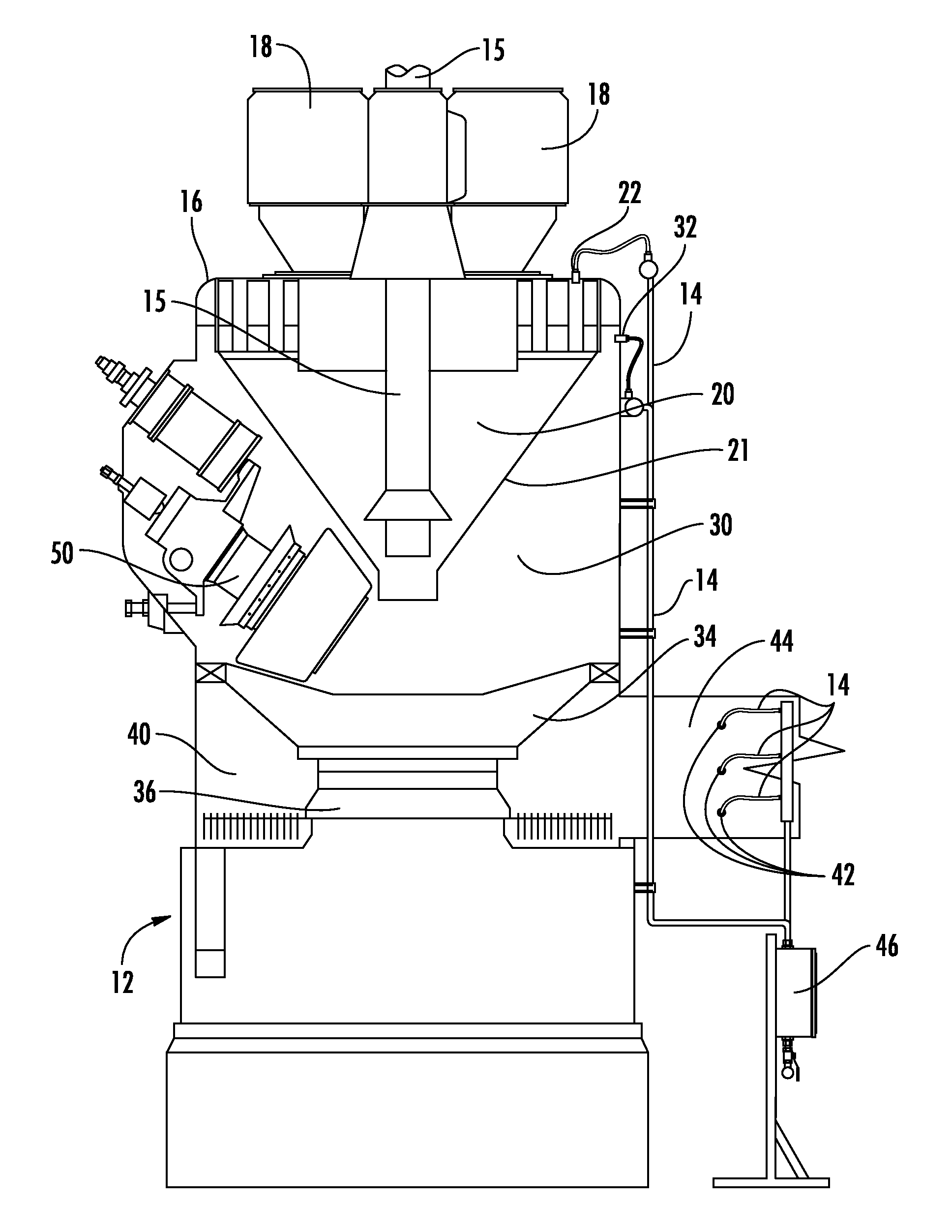
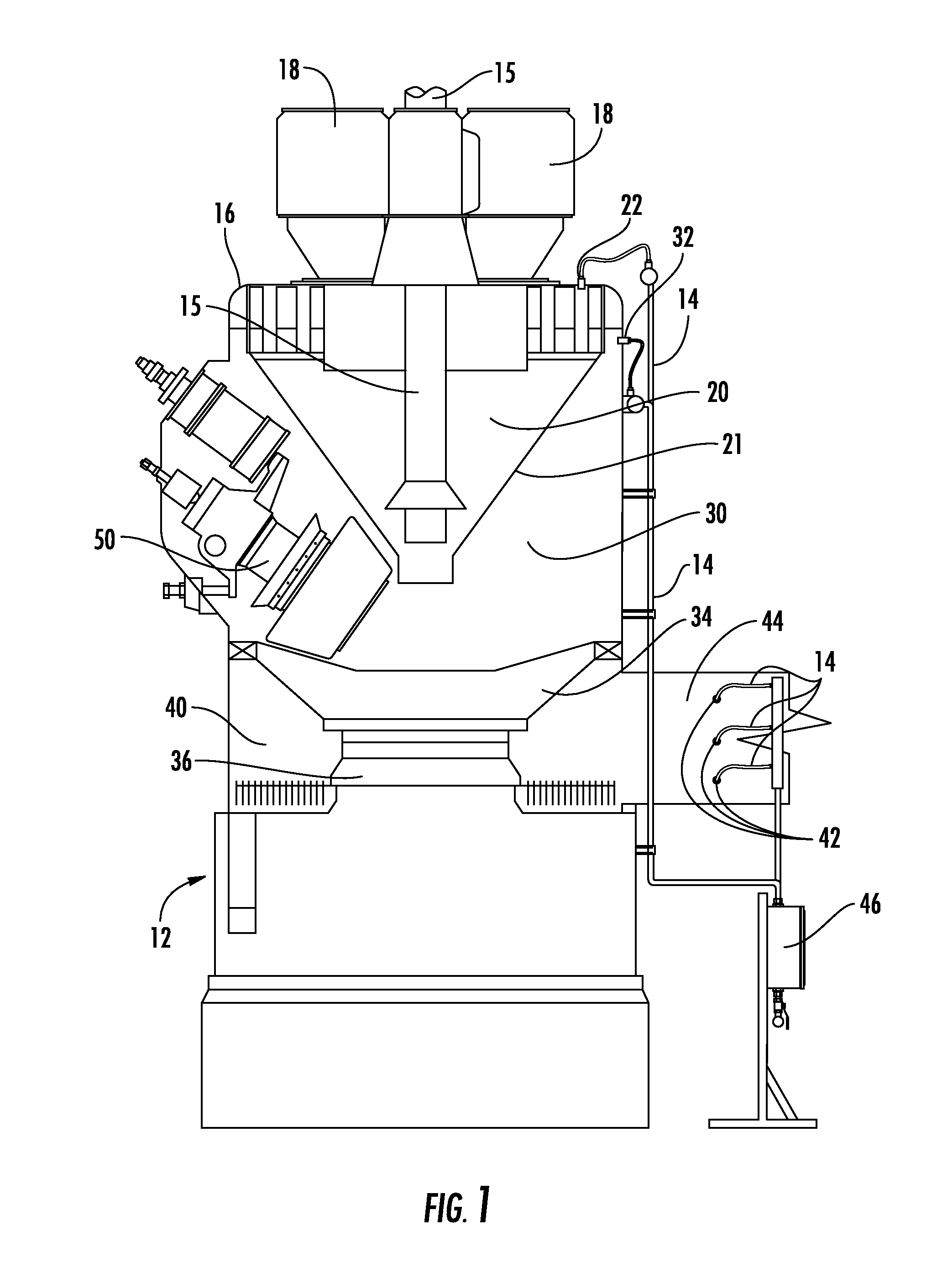
With vertical spindle style mills, a loss of
airflow during such a trip means that coal that previously was suspended above the
grinding bowl or table falls down to the hot underbowl area where temperatures often exceed 650° F. In this high temperature region of the mill, coal quickly dries and, especially in the case of PRB coal and similar highly volatile coals, spontaneously ignites and begins to smolder.
Often these accumulations or mounds of coal are smoldering or burning because they have settled into a high temperature area of the coal mill, and are agitated and suspended in air.
Once suspended, more surface area is exposed to
oxygen, resulting in the often catastrophic combination of high air-to-fuel ratio, high temperatures and an ignition source that could result in an explosion.
The resulting rise in temperature causes any coal remaining in the mill to dry and ignite.
Left undetected, such fires can grow into major issues when primary
airflow is reintroduced.
While manual startup and shutdown is often preferred over automatic routines for a variety of reasons, a small oversight on the part of the operator may lead to catastrophic events.
If coal is introduced too late into the startup procedure for temperatures to be kept below blast gate trip temperatures, again the hazardous combination of high temperatures and dry coal is likely.
During shutdown, if an operator fails to stop hot
airflow when fuel feed is stopped, air-to-fuel ratio and temperature will go high, increasing the potential of an explosion or fire.
Mill fires have been known to erupt because a mill, still loaded with coal, which has been isolated from air supply, is opened for inspection.
These fires most often occur when a mill has not fully cooled to ambient temperatures.
This
scenario may lead to injury or death.
Improperly maintained or otherwise malfunctioning equipment or measurement
instrumentation is another major cause of mill fires.
Coal feed interruptions, resulting from mechanical issues or plugged coal feed pipes, often result in high temperatures and air-to-fuel ratios.
Improper airflow or temperature indications also have the potential of causing issues.
For instance, an indicated temperature that is much lower than actual mill outlet temperature can lead to driving the mill temperature dangerously high.
Improper airflow indication has the potential to lead to coal
spillage into the underbowl because of insufficient airflow.
Stuck or otherwise compromised hot or
cold air dampers also have the potential of causing high temperatures, insufficient velocities or high air-to-fuel ratios, while worn or eroded pulverizer components may allow for coal to settle or spill over into the underbowl.
While inerting is effective at extinguishing smoldering or burning materials inside the mill, this method only works when a mill is isolated.
However, if a
damper leak is detected or an improper measurement of media flow rate, this may lead to
oxygen levels that exceed the intended ten to fourteen percent
oxygen by volume.
Without reliable and continuous O2 measurement, such issues may go undetected.
Generally, steam cannot be relied upon to extinguish a fire.
These methods are purely reactive and result in pulverizer
downtime and unit derates.
In either case, further
downtime is incurred since the mill must be thoroughly inspected after an explosion.
This usually manifests itself as a temperature excursion where mill outlet or
discharge temperature is abnormally high.
There is a high risk of fires or puff evolving while mill outlet temperature is abnormally high.
Such incidents can damage or completely destroy the mill and ancillary equipment.
Another concern is combustible dusts on and around ancillary equipment in the area that can result in secondary explosions or fires.
To address internal mill fires, most fire suppression systems known in the art douse the mill externally with water, and are ineffective at suppressing fires inside the classifier and
grinding / pulverization zones of coal mill / pulverizers.
These methods typically require several hours to completely suppress a fire and most often do not suppress the fire quickly enough to prevent substantial damage to the mill or pulverizer
system.
Heat and combustibles, such as gases and
coal dust remaining in the mill after suppression, present the risk of re-ignition.
The high temperatures inside the mill after suppression mean that a long cooling period is required before maintenance crews may enter the mill to assess and repair damage.
Raw coal supply interruptions due to imprecise feeder control and stoppages above and below the feeder are another
common source of fires and puffs.
Interruptions in raw coal feed can be caused by environmental conditions such as frozen coal, wet coal from
precipitation and mechanical anomalies such as broken feeder belts, seized bearings and other causes.
Also, accumulations of raw coal that has spilled over into the under bowl section are exposed to temperatures of 500° F. to 750° F. while firing sub-
bituminous coal, and are another common cause of mill fires.



