Spread spectrum clock generator, electronic apparatus, and spread spectrum clock generation method

Active Publication Date: 2016-04-07
RICOH KK
View PDF8 Cites 5 Cited by
  • Summary
  • Abstract
  • Description
  • Claims
  • Application Information

AI Technical Summary

Benefits of technology

[0008]Embodiments of the present invention provide a novel spread spectrum clock generator that includes a phase comparator that compares a reference clock with a feedback clock, a low-pass filter that passes a predetermined low-frequency component from a signal of the comparison result, a phase lock loop that includes a voltage-controlled oscillator that generates an output clock whose frequency corresponds to the filtered signal, a triangular wave controller that generates a triangular wave signal for frequency-modulating the spread spectrum clock based on the output clock, a delay controller that generates the fe

Problems solved by technology

However, in a phase-locked loop (PLL) that generates the spread spectrum clock, particularly using a center spread method, even using triangular wave

Method used


Image

  • Spread spectrum clock generator, electronic apparatus, and spread spectrum clock generation method
  • Spread spectrum clock generator, electronic apparatus, and spread spectrum clock generation method
  • Spread spectrum clock generator, electronic apparatus, and spread spectrum clock generation method

Examples


embodiment 1

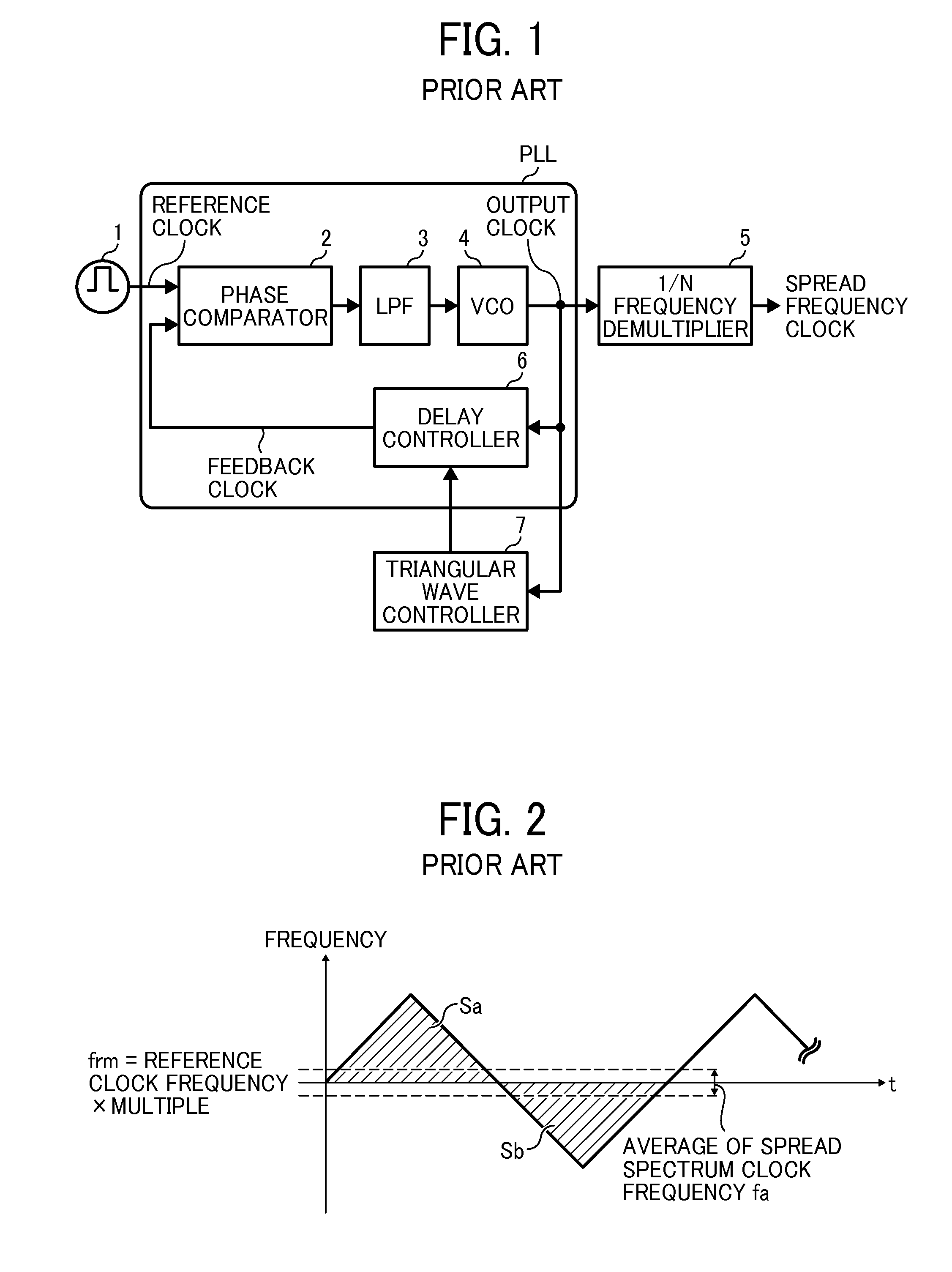
[0024]Furthermore, in the spread spectrum clock generator using the center spread method that multiplies the reference clock by a multiple, it is preferable that the average frequency of the spread spectrum clock matches the reference frequency frm indicated by x-axis in FIG. 2. However, actually, due to analog characteristics of the LPF 3 and circuit characteristics of the delay controller 6 in FIG. 1, even if the ideal triangular wave signal is used for delay control of the spread spectrum clock, usually the result is above the x-axis or below the x-axis. Here, in the ideal triangular wave signal, the area Sa on the plus-side of the reference frequency frm of the spread spectrum clock in FIG. 2 is the same as the area Sb on the minus-side of the reference frequency frm (i.e., their absolute integrated values are the same). In this case, if an ideal average frequency is achieved using the LPF 3 as an analog circuit with an attached analog circuit or the delay control circuit, typic...

embodiment 2

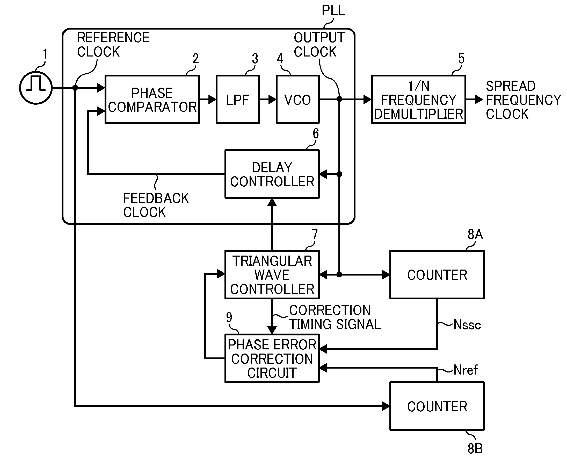
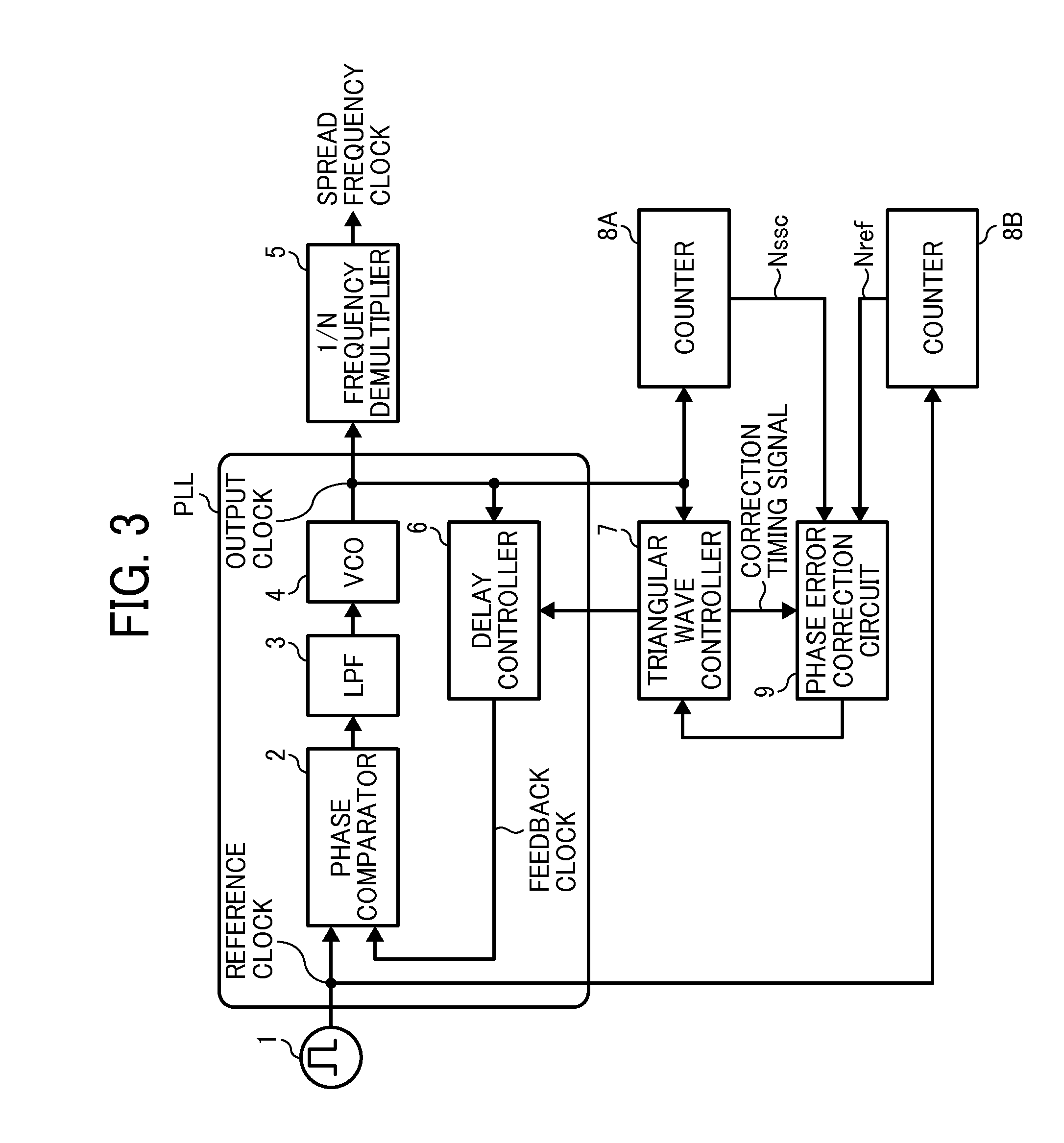
[0043]As described above, in this embodiment, the phase error correction circuit 9 compares the count value Nssc with the count value Nref for each frequency modulation period. Subsequently, in accordance with the comparison result, the phase error correction circuit 9 performs the phase error correction process so that the count value Nref gets close to the count value Nssc (i.e., the frequency of the output clock fssc gets close to the frequency of the reference clock fref substantially). As a result, in the spread spectrum clock generator using the PLL, it is possible to minimize the phase error, and it is possible that the frequency of the spread spectrum clock gets close to the frequency of the reference clock substantially. Embodiment 2 FIG. 5 is a diagram illustrating a waveform of the digital triangular wave signal for frequency modulation to explain a phase error correction process performed by a phase error correction circuit 9 in this embodiment. The delay controller 6 in...

embodiment 3

[0048]In this embodiment, in the operation (B), if Nssc is larger than Nref, in the subsequent frequency modulation period, the phase error correction circuit 9 generates the triangular wave signal whose minimum value period Nb is (n+1)Tc. It should be noted that the case described above is an example, and it is possible that the phase error correction circuit 9 generates the triangular wave signal whose maximum value period Nu is (n−1)Tc. Embodiment 3 FIG. 6 is a diagram illustrating a waveform of the digital triangular wave signal for frequency modulation to explain a phase error correction process performed by the phase error correction circuit 9 in this embodiment. In the embodiments 1 and 2, the phase error correction process is performed for each period of the frequency modulation period. However, in this embodiment, the phase error correction circuit 9 performs the phase error correction process for each period that the frequency modulation period is multiplied by a multiple ...


PUM


Abstract

A spread spectrum clock generator includes a phase comparator that compares a reference clock with a feedback clock, a low-pass filter that passes a predetermined low-frequency component, a phase lock loop that includes a voltage-controlled oscillator generating an output clock whose frequency corresponds to the filtered signal, a triangular wave controller that generates a triangular wave signal for frequency-modulating the spread spectrum clock based on the output clock, a delay controller that generates the feedback clock by controlling delay of the output clock based on the triangular wave signal, a first counter that counts the output clock and output a first count value, a second counter that counts the reference clock and output a second count value, and a phase error correction circuit that compares the first count value with the second count value and corrects phase error of the output clock.

Description

CROSS-REFERENCE TO RELATED APPLICATIONS[0001]This patent application is based on and claims priority pursuant to 35 U.S.C. §119(a) to Japanese Patent Application Nos. 2014-204495, filed on Oct. 3, 2014 and 2015-143581, filed on Jul. 21, 2015 in the Japan Patent Office, the entire disclosures of which are hereby incorporated by reference herein.BACKGROUND[0002]1. Technical Field[0003]The present invention relates to a spread spectrum clock generator, an electronic apparatus incorporating the spread spectrum clock generator, and a spread spectrum clock generation method.[0004]2. Background Art[0005]A spread spectrum clock is used to reduce electromagnetic interference (EMI).[0006]However, in a phase-locked loop (PLL) that generates the spread spectrum clock, particularly using a center spread method, even using triangular wave data to control the frequency spread, it is possible to generate a phase error between the reference clock of the PLL and the spread spectrum clock.[0007]To cop...

Claims


Application Information

Patent Timeline
IPC IPC(8): H03L7/08H03K4/06
CPCH03K4/06H03L7/0805H03K3/64H03K3/78H03L7/06H03L7/081H03L7/10H03L7/16
Inventor IWASAKI, KEIICHI
Owner RICOH KK
Why Eureka
Try Eureka