
Electrical servo power-assisted steering controller

A technology of power steering and electric servo, which is applied in the direction of electric steering mechanism, AC motor control, control system, etc., can solve the problems of small power assist current, uneven transition, complex control circuit structure, etc., and meet the requirements of reducing performance and dead zone The effect of smooth transition and expanding the scope of application

Inactive Publication Date: 2008-01-23
ZHEJIANG UNIV +1
View PDF0 Cites 32 Cited by
  • Summary
  • Abstract
  • Description
  • Claims
  • Application Information

AI Technical Summary

Problems solved by technology

This scheme of using an independent mos tube to build an H-bridge drive motor has the following disadvantages: an independent mos tube requires a drive circuit, and driving a high-end PNP type mos tube requires a booster circuit to provide a voltage higher than the power supply, resulting in the entire control circuit structure Complicated; due to the manufacturing process of mos tubes, the boost current is relatively small and cannot provide a large boost, which limits the application of the system
The disadvantage of this digital control scheme is: the torque signal required by the controller for calculation is obtained through A / D sampling, but the sampling accuracy of A / D sampling and the limitation of sampling speed make the control accuracy of the controller relatively poor; the microprocessor according to A lot of calculations are required to obtain the motor current given signal from the torque and vehicle speed signals, but the calculation speed of the general microprocessor is not fast enough, so that the system has obvious lag, slow response, unsatisfactory control effect, and even vibration under severe conditions;
[0007] When the torque input is relatively small, the controller using the motor unipolar drive scheme, the program stored in the microprocessor will set the current reference to 0, that is, there is a central dead zone, but due to the inertia of the motor, the transition is not smooth at cold start , feel bad

Method used


Image

  • Electrical servo power-assisted steering controller
  • Electrical servo power-assisted steering controller
  • Electrical servo power-assisted steering controller

Examples


Embodiment Construction

[0023] Further illustrate the present invention below in conjunction with accompanying drawing.

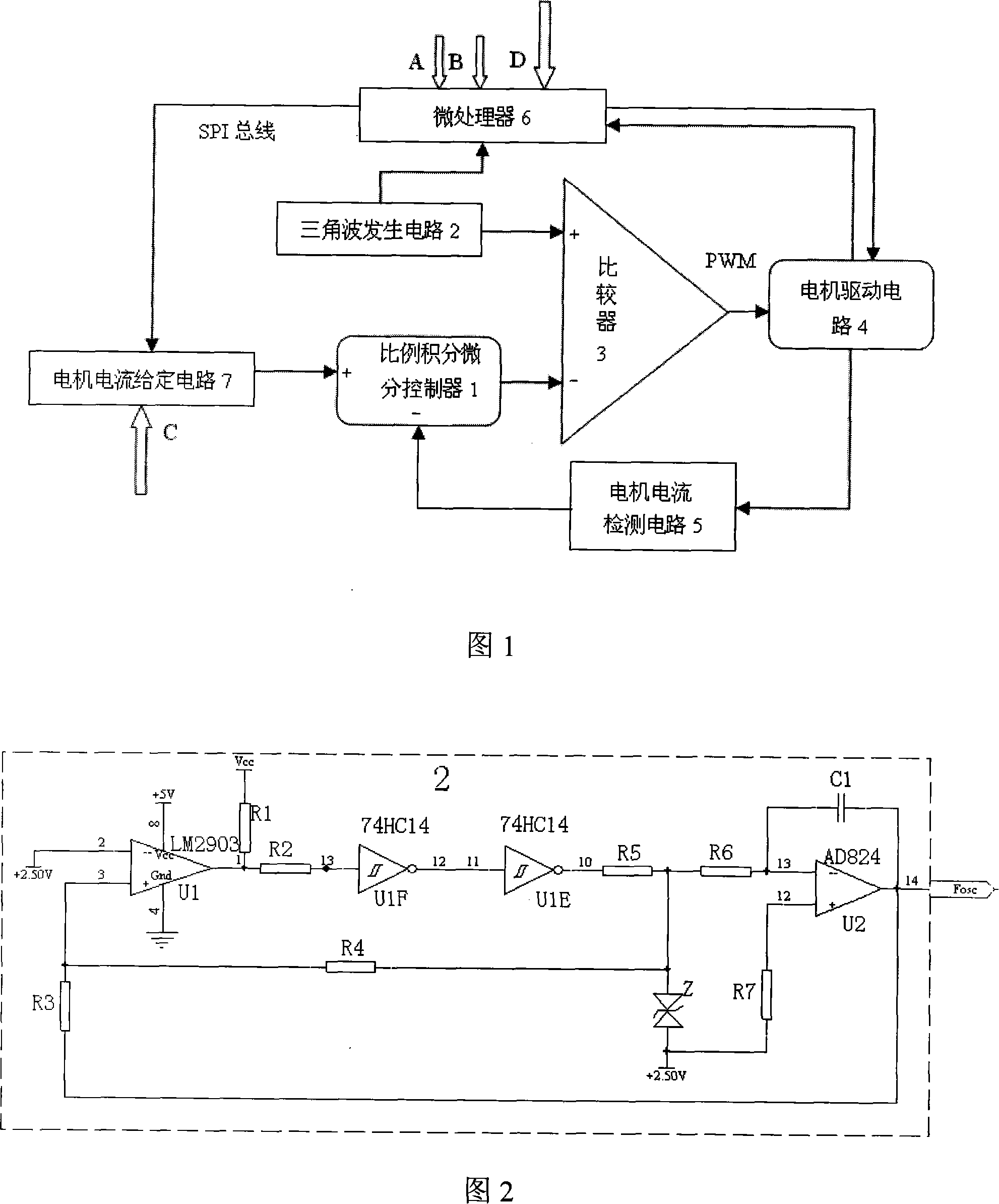
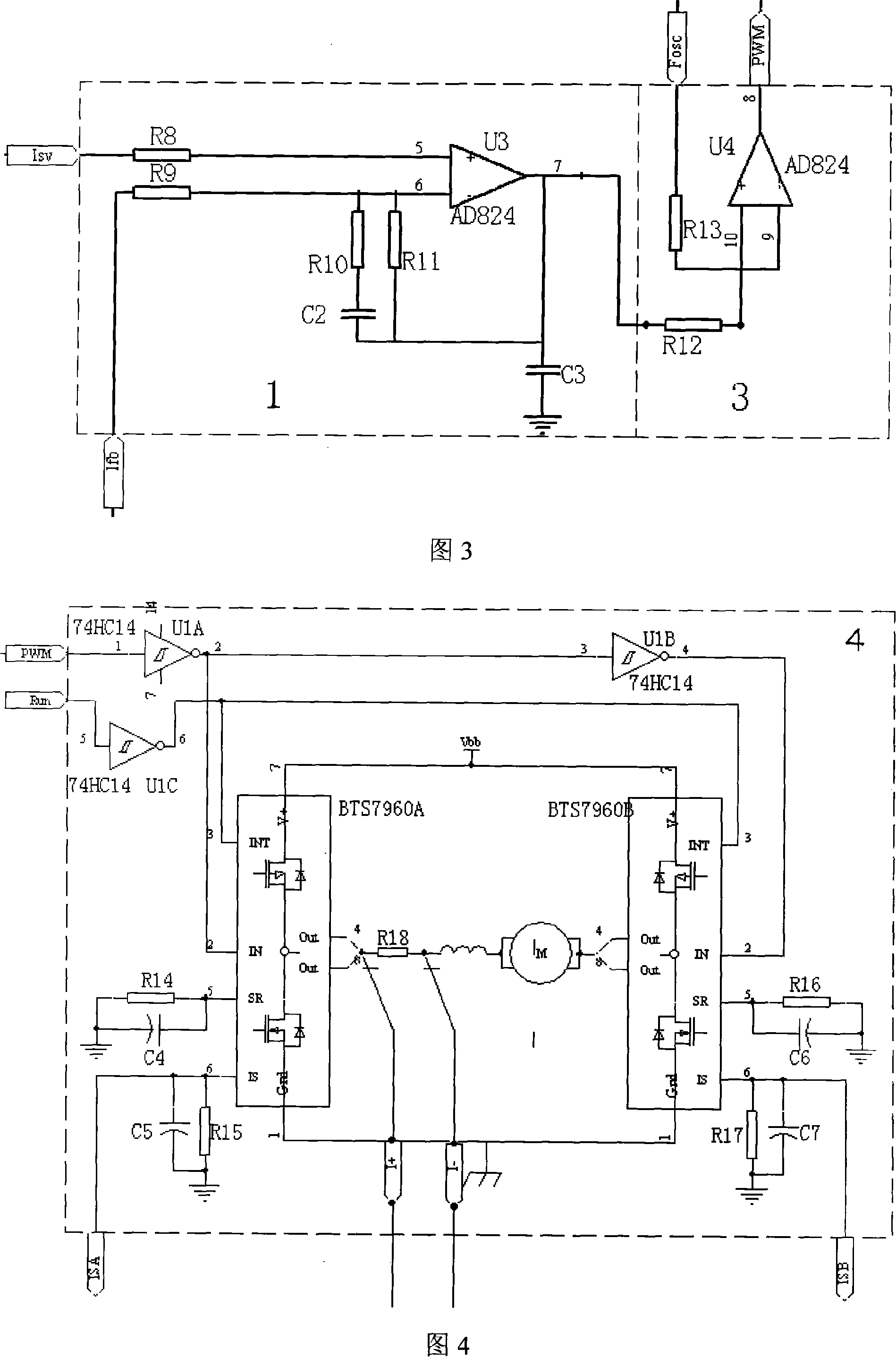
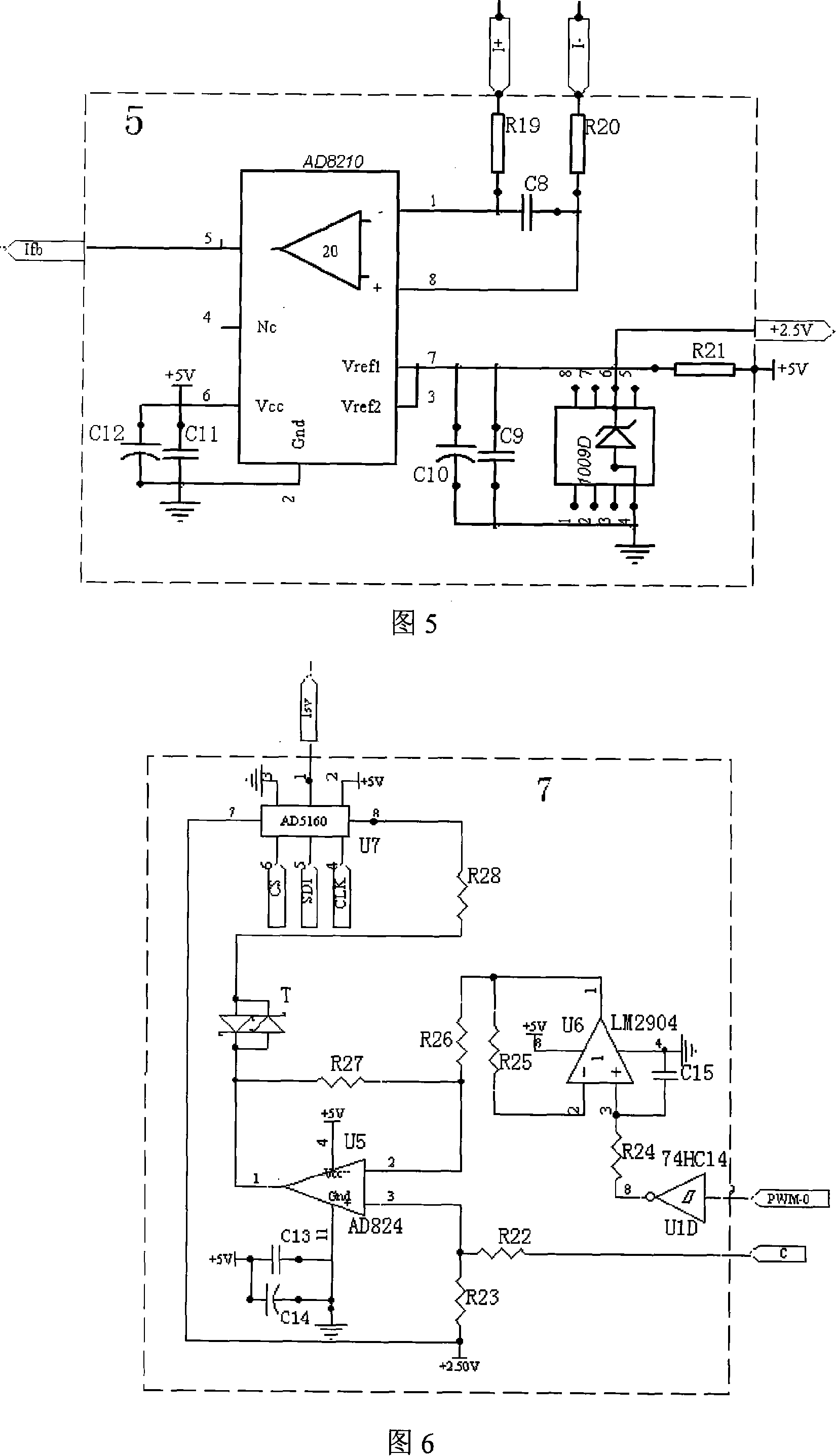
[0024] Referring to Fig. 1, the electric servo power steering controller of the present invention comprises a proportional integral differential controller 1, a triangular wave generator 2, a comparator 3, a motor drive circuit 4, a motor current detection circuit 5, a microprocessor 6 and a motor current supply The fixed circuit 7, the microprocessor 6 collects the vehicle speed signal A and the engine speed signal B, and one of its control signal output terminals is connected with an input terminal of the motor current given circuit 7 through the SPI bus, and another control signal of the microprocessor 6 The output terminal is connected to the input terminal of the motor drive circuit 4; the external signal input terminal of the motor current given circuit 7 is connected to the main torque signal C output by the torque sensor, and the voltage signal output by the motor current g...


PUM


Abstract

The present invention discloses an electrical servo steering controller, which comprises a PID controller, a triangular wave generating circuit, a comparator, a motor current detecting circuit, a motor drive circuit, a microprocessor and a motor current setting circuit. Wherein, the PID controller outputs an adjusting voltage to the comparator according to a difference between a motor current setting signal output by the motor current setting circuit and a motor current detecting signal output by the motor current detecting circuit. The comparator compares a triangular wave signal output by the triangular wave generating circuit to output a pulse width modulation signal to the motor drive circuit to control the motor current. The microprocessor works out and controls a resistance value of a digital potential device in the motor current setting circuit to modify a servo characteristic. An analog circuit is adopted to complete main functions. Besides, a special motor drive chip can provide a higher servo force and ensure a larger applicable scope, simple circuit control, wonderful steering feeling and higher reliability.

Description

technical field [0001] The invention relates to a controller of an electric servo power steering system, which is suitable for small vehicles with small steering power and equipped with a steering shaft power assist type electric power steering system. Background technique [0002] The technology of the hydraulic power steering system is relatively mature, and it is the most widely used power steering system in automobiles. But it has many shortcomings. First, the boost effect is fixed, and the boost characteristics cannot be adjusted according to the change of vehicle speed, which makes it difficult to solve the contradiction between portability at low speed and stability at high speed; second, the engine must always drive the hydraulic pressure. The pump runs to maintain the oil pressure of the system, resulting in an increase in fuel consumption; third, the leakage of the hydraulic oil in the system causes pollution, and it is difficult to dispose of waste hydraulic oil. ...

Claims


Application Information

Patent Timeline
IPC IPC(8): H02P23/00B62D5/04
Inventor 吴锋杨志家姚栋伟胡树根王耘
Owner ZHEJIANG UNIV
Learn More