Load drive system, motor drive system, and vehicle control system

a technology of load drive and motor drive, which is applied in the direction of motor/generator/converter stopper, electric energy management, electric devices, etc., can solve the problem of cancelling the switching noise generated by the switching by the other side, and achieve the effect of preventing the overlap of three types of switching noise, reducing noise, and further reducing nois

Inactive Publication Date: 2011-10-27
PANASONIC CORP
View PDF7 Cites 31 Cited by
  • Summary
  • Abstract
  • Description
  • Claims
  • Application Information

AI Technical Summary

Benefits of technology

[0014]According to the present invention, switching in opposite state transition directions is made in the first and the second three-phase inverters, whereby noise is cancelled out by each other. Furthermore, regarding the triangular waveform used as the third carrier signal, there is no time point when the voltage instantly drops or instantly increases as can be seen in the sawtooth waveform. Accordingly, in the triangular waveform, a magnitude relation between a control signal and the carrier signal cannot be reversed simultaneously with respect to all of U-phase, V-phase, and W-phase. This prevents the situation where the switching in a same state transition direction is made simultaneously in all of U-phase, V-phase, and W-phase in the third three-phase inverter. As a result, overlap of three types of switching noise is prevented. Accordingly, compared with a case where the sawtooth wave voltage is used as the third carrier signal, the noise is reduced.
[0015]Furthermore, the third carrier signal

Problems solved by technology

This means that the switching noise generated b

Method used


Image

  • Load drive system, motor drive system, and vehicle control system
  • Load drive system, motor drive system, and vehicle control system
  • Load drive system, motor drive system, and vehicle control system

Examples


first embodiment

[0035]

[0036](Load Drive System 100)

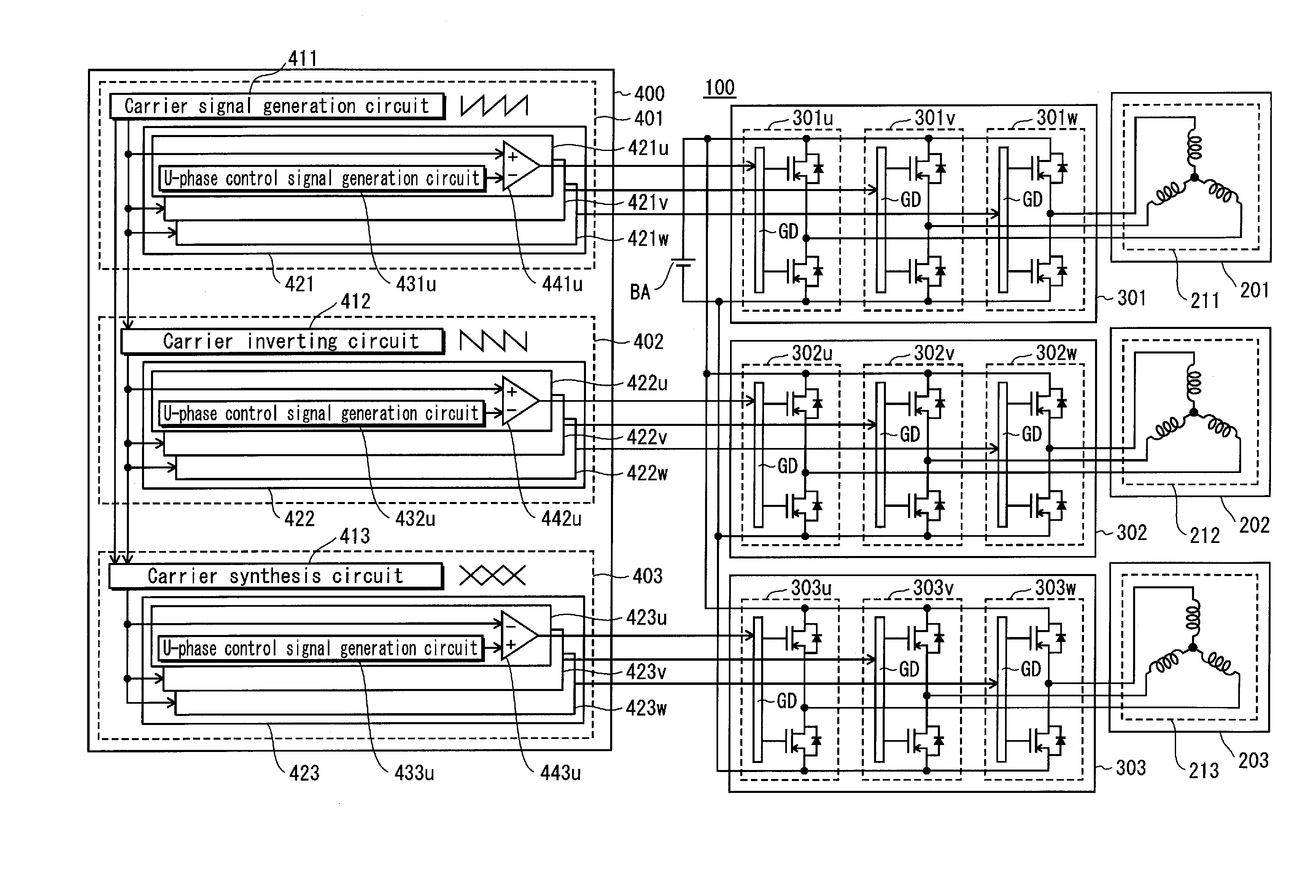
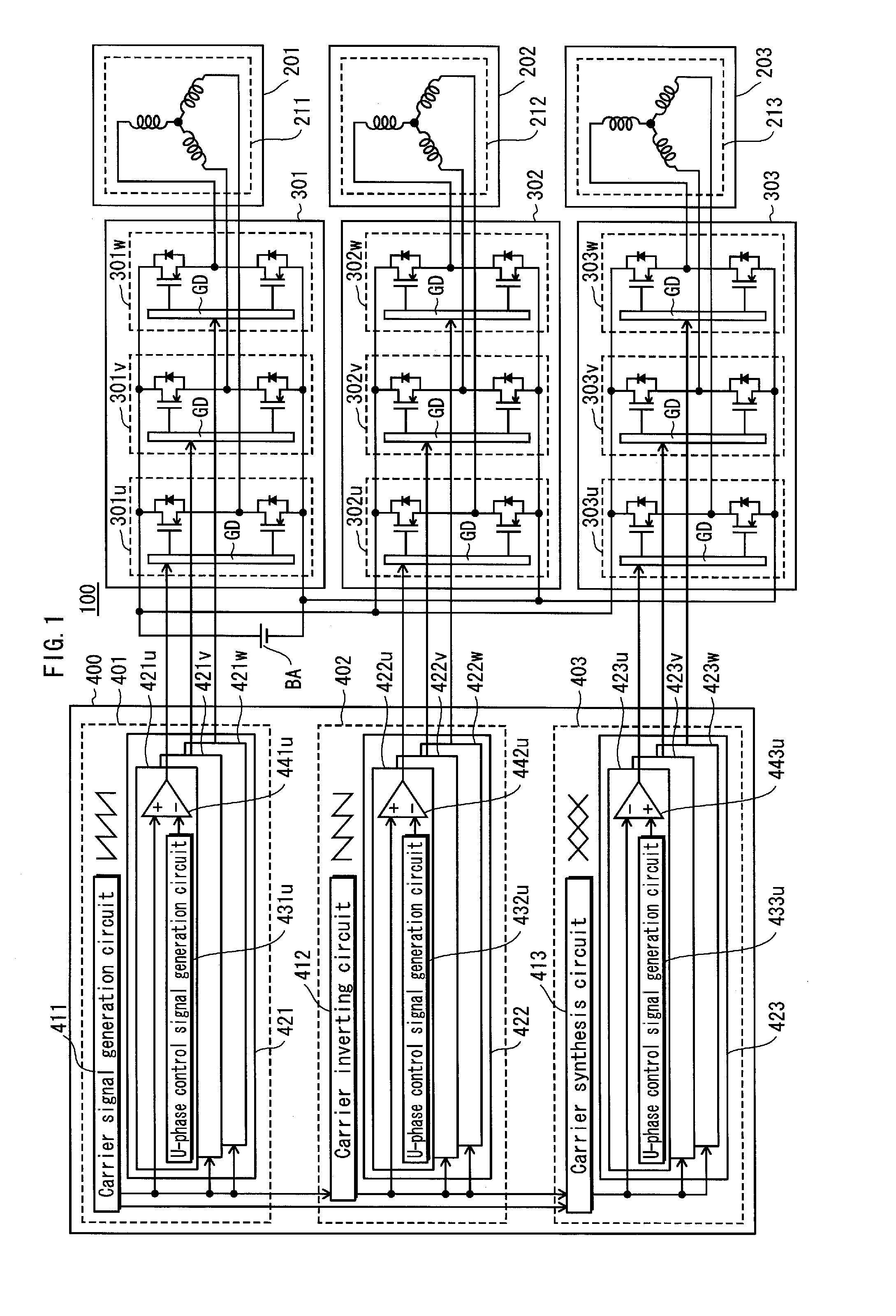
[0037]FIG. 1 shows an overall structure of a load drive system according to a first embodiment of the present invention.

[0038]A load drive system 100 includes a direct current battery BA, three-phase alternative current motors 201, 202, and 203, three-phase inverters 301,302, and 303, and a control circuit 400.

[0039]The direct current battery BA is a direct current power source obtained by rectifying commercial power source, or a direct current power of a battery type (such as a nickel hydride second battery and a lithium-ion secondary battery).

[0040]The three-phase alternative current motor 201 includes a three-phase coil 211 to which a three-phase current is supplied. The three-phase alternative current motor 202 includes a three-phase coil 212 to which a three-phase current is supplied. Regarding the three-phase alternative current motor 203, a difference from the three-phase alternative current motor 201 lies in a point that a three-phase coil ...

second embodiment

[0087]

[0088](Load Drive System 110)

[0089]FIG. 5 shows an overall structure of the load drive system according to a second embodiment of the present invention. A load drive system 110 shown in FIG. 5 includes a three-phase alternative current motor 204, a three-phase inverter 304, and a control circuit 410, as replacement for the three-phase alternative current motor 203, the three-phase inverter 303, and the control circuit 400 included in the load drive system 100 shown in FIG. 1. The following describes the structure of the load drive system 110 that differs from the load drive system 100 according to the first embodiment.

[0090]The three-phase alternative current motor 204 includes a three-phase coil 214 to which a three-phase current is supplied. A difference from the three-phase alternative current motor 203 lies in a point that the three-phase coil 214 is wound in the direction opposite to the three-phase coil 213 according to the first embodiment. That is to say, in the presen...

third embodiment

[0112]

[0113](Load Drive System 120)

[0114]FIG. 8 shows an overall structure of the load drive system according to a third embodiment of the present invention. A load drive system 120 shown in FIG. 8 includes a three-phase alternative current motor 205, a three-phase inverter 305, and a control circuit 420, as replacement for the three-phase alternative current motor 203, the three-phase inverter 303, and the control circuit 400 included in the load drive system 100 shown in FIG. 1. The following describes the structure of the load drive system 120 that differs from the load drive system 100 according to the first embodiment.

[0115]The three-phase alternative current motor 205 includes a three-phase coil 215 to which a three-phase current is supplied. The three-phase coil 215 has the same structure as the three-phase coil 213 of the first embodiment. In other words, the three-phase coil is wound in the direction opposite to the three-phase coils 211 and 212.

[0116]The three-phase invert...


PUM


Abstract

Provided is a small-sized load drive system which, even with three three-phase inverters, significantly reduces noise regardless of control duty ratio. The load drive system includes three-phase inverters 301 to 303, and first, second, and third control units 401 to 403. The inverters 301 to 303 are connected to loads 211 to 213, respectively. The first control unit 401 generates sawtooth wave voltage and controls the inverter 301 according to the sawtooth wave voltage. The second control unit 402 generates inverse sawtooth wave voltage and controls the inverter 302 according to the inverse sawtooth wave voltage. The third control unit 403 generates triangular wave voltage which has ramps respectively equal to the sawtooth/inverse sawtooth wave voltage and either has a same phase or is out of phase by half a period relative to the sawtooth/inverse sawtooth wave voltage, and also controls the inverter 303 according to the triangular wave voltage.

Description

TECHNICAL FIELD[0001]The present invention relates to noise reduction techniques used in load drive systems, in particular in the load drive systems using PWM control, for driving a load, such as a motor.BACKGROUND ART[0002]Among the load drive systems, a motor drive system is used in a wide range of fields. The motor drive system includes a three-phase alternative current motor (may be referred to below simply as a motor), a three-phase inverter that converts a direct current to an alternative current to supply the converted current to the motor, and a control unit that controls the three-phase inverter. For example, as a main motor for use in an electrical vehicle and a hybrid vehicle, an interior permanent magnet motor, in other words a brushless DC motor is employed.[0003]As a method for obtaining a sine wave output voltage from the three-phase inverter, PWM (Pulse Width Modulation) control is generally used. In the PWM control, switching operations are performed at a high speed...

Claims


Application Information

Patent Timeline
IPC IPC(8): H02P6/04H02M1/15H02P6/10H02J3/01H02M1/12H02M7/48H02M7/493H02P5/68H02P5/74
CPCB60L11/1803H02M7/53871Y02T10/7005H02P27/08Y02T10/642H02M2001/008B60L1/003B60L1/02B60L15/08B60L2210/40B60L2220/14B60L2220/16B60L2220/46B60L2270/147B60L50/51H02M1/008Y02T10/64Y02T10/70Y02T10/72
Inventor KAZAMA, SHUNKITABATAKE, MAKOTOTAGOME, MASAKI
Owner PANASONIC CORP
Why Eureka
Try Eureka