Generating electricity from air resistance caused by a moving vehicle

Active Publication Date: 2016-04-14
KARIMIROZBAHANI MEHDI
View PDF56 Cites 0 Cited by
  • Summary
  • Abstract
  • Description
  • Claims
  • Application Information

AI Technical Summary

Benefits of technology

[0007]A system for generating electricity is provided. The system includes a vehicle and a wind turbine installed at one end of the vehicle. The wind turbine includes a set of input ports and a set of exit ports. The wind turbine, the set of input ports, and the set of exit ports can be located symmetrically on the vehicle body. Airflow, generated around the vehicle when the vehicle motions forward, can enter the wind turbine via the set of input ports and exits via the set of output ports causing the wind turbine to rotate and generate the electricity. The airflow around the vehicle can rotate the wind turbine without increasing drag forces generated due to friction between air and the vehicle body. The wind turbine can be installed at the one end of the vehicle during manufacturing of the vehicle. The wind tur

Problems solved by technology

However, the systems suggested by those known technologies include installing stationery devices to harness the wind energy when vehicles motion against the stations where the devices are installed and as a result in such systems when there is no vehicle traffic on the road or the track, no energy can be generated.
The reduction of drag forces may reduce air resistance against vehicle motion.
Furthermore, installing the wind turbines in this way may result in generation of electricity from wind even when the vehicle is s

Method used


Image

  • Generating electricity from air resistance caused by a moving vehicle
  • Generating electricity from air resistance caused by a moving vehicle
  • Generating electricity from air resistance caused by a moving vehicle

Examples


Example

[0016]In the following detailed description, numerous specific details are set forth by way of examples in order to provide a thorough understanding of the relevant teachings. However, it should be apparent to those skilled in the art that the present teachings may be practiced without such details. In other instances, well known methods, procedures, components, and / or circuitry have been described at a relatively high-level, without detail, in order to avoid unnecessarily obscuring aspects of the present teachings.

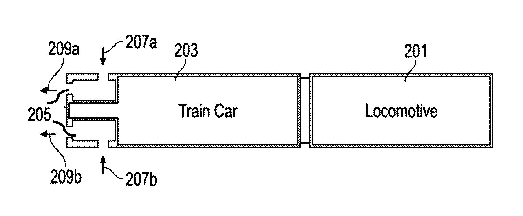
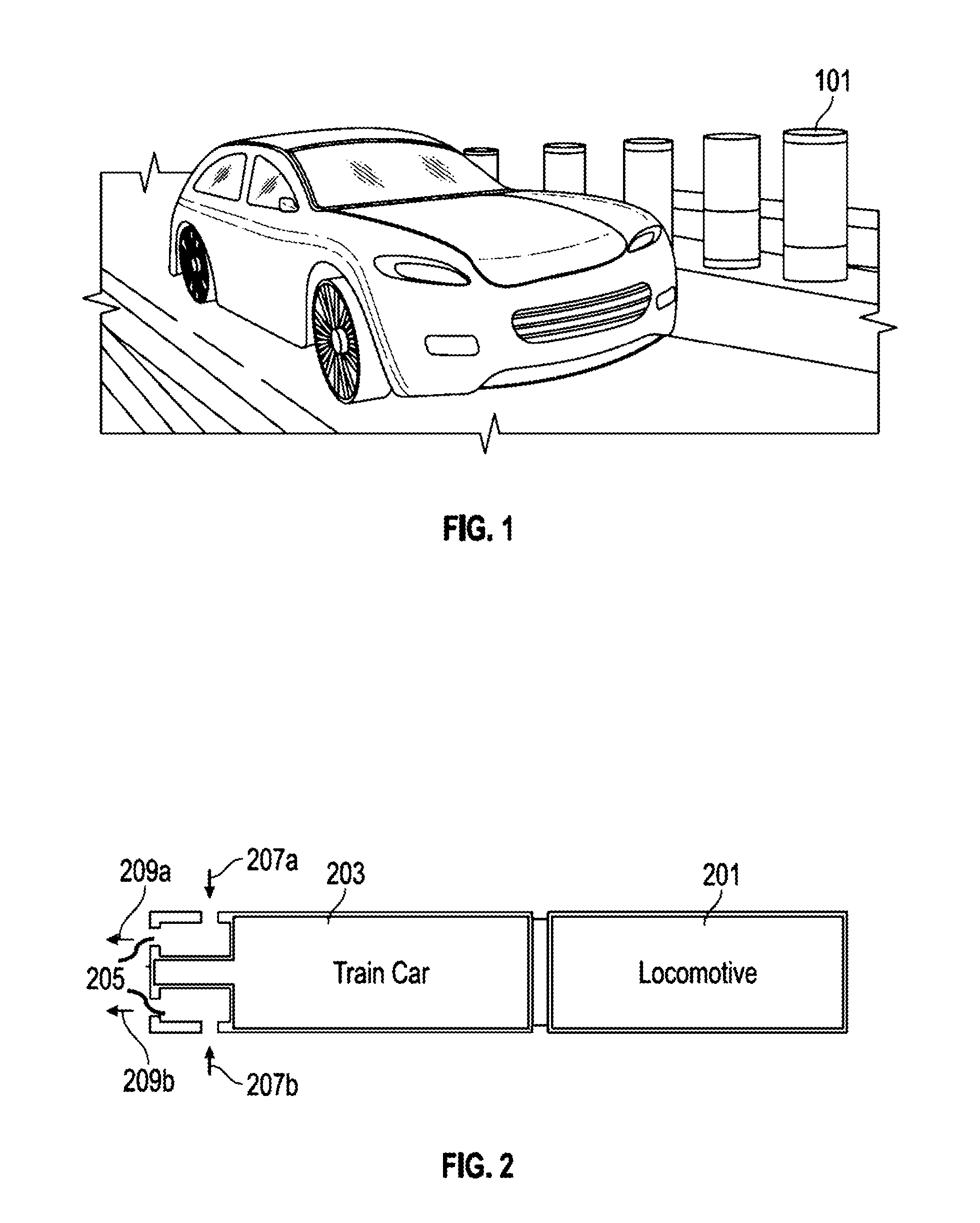
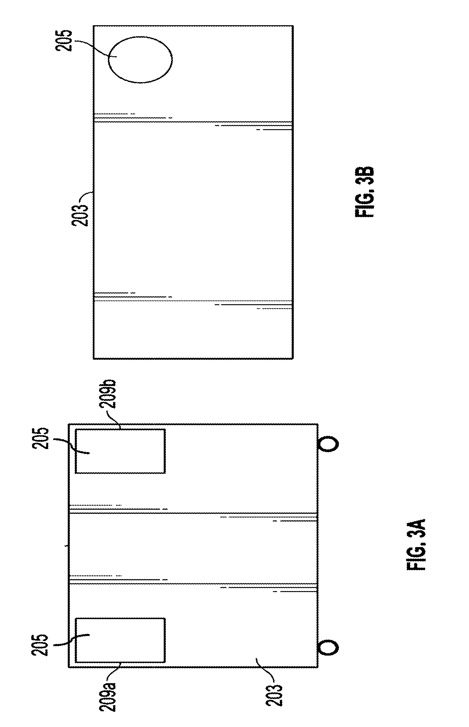
[0017]The instant application relates to a system for harnessing air resistance or drag energy generated from a vehicular movement and converting the harnessed drag energy into electricity. The system may include one or more wind turbines installed on the vehicle (e.g., a train) to rotate with the wind generated from the vehicular movement. In addition to power generation, the system can reduce air resistance against the vehicle movement direction. Moreover, the system de...


PUM


Abstract

A system for generating electricity is provided. The system includes a vehicle and a wind turbine installed at one end of the vehicle. The wind turbine includes a plurality of input ports and a plurality of exit ports. The airflow around the vehicle enters the wind turbine via the plurality of input ports and exits the wind turbine via the plurality of exit ports causing the wind turbine to rotate and generate electricity.

Description

CROSS REFERENCE TO RELATED APPLICATION[0001]This application claims the benefit of priority to an Iran patent application having Iran Patent Application Serial Number 139350140003007705, filed on Oct. 12, 2014 and issued as Iran Patent Number 85207 on Mar. 4, 2015, the entire content of which is incorporated herein by reference.TECHNICAL FIELD[0002]The present application relates generally to harnessing air resistance or drag energy generated from a vehicle movement and, more particularly, to a system for converting harnessed drag energy into electricity.BACKGROUND[0003]Wind turbines have been long used for harnessing wind energy and converting the harnessed energy into other types of energy such as electricity. These turbines are typically stationary and installed in a certain location to convert kinetic energy from the wind into electricity.[0004]On the other hand, motion of vehicles, such as trains, with high speeds generate a drag force, also referred to as air resistance which ...

Claims


Application Information

Patent Timeline
IPC IPC(8): B60R16/03F03D9/00
CPCF03D9/002B60R16/0307F03D9/25F03D9/32F05B2240/941Y02E10/72Y02E10/728
Inventor KARIMIROZBAHANI, MEHDI
Owner KARIMIROZBAHANI MEHDI
Why Eureka
Try Eureka